• You can now help support WorldwideDX when you shop on Amazon at no additional cost to you! Simply follow this Shop on Amazon link first and a portion of any purchase is sent to WorldwideDX to help with site costs.

Homebrew Merlin Experiment

HomerBB

Sr. Member
Jan 4, 2009
3,933
2,633
273
68
Rogers, Ar
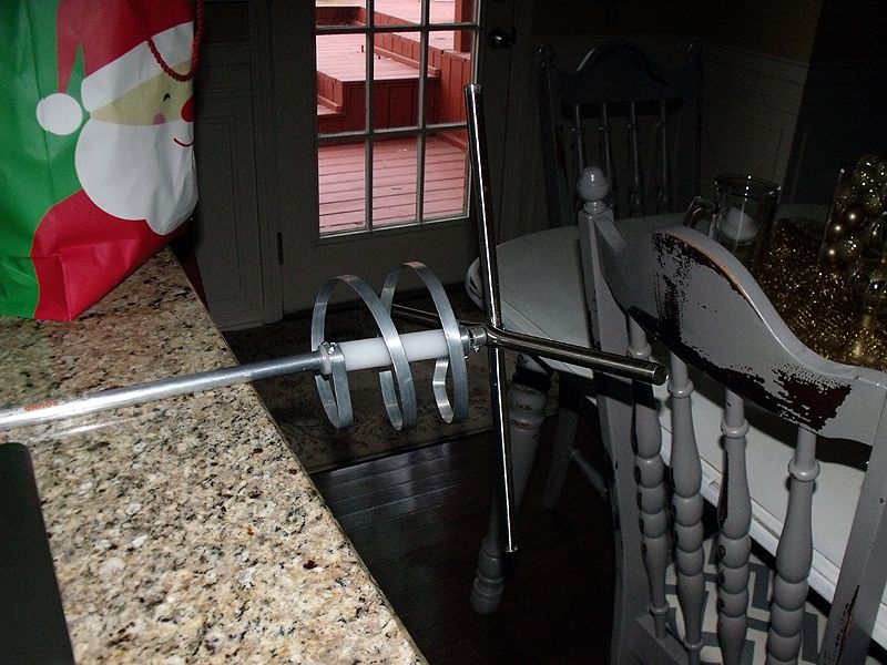
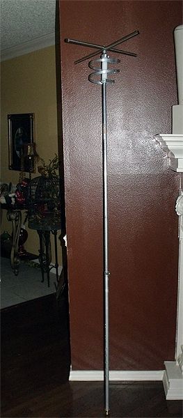
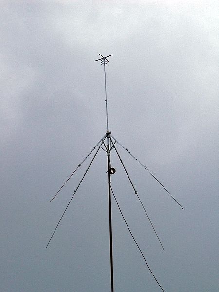
Okay, I am in the process of transforming the 1/4ƛ GP - Clothes Line Groundplane - into a Merlin style antenna. I have some more details to attend to

get it where I want it - radials at a greater angle, improvement to the CMC choke, and shortening the length.

I truly wish I had first hand experience with the Merlin in order to be certain of every single detail of it, but I am

proceeding anyway with what I have been able to glean by reading threads across the www. There isn't much out there from

the manufacturer, and most of what I've read in the way of arguing for or against it has not offered any substantial

details about the antenna itself. Anecdotal info is abundant, but little else of use for replicating the antenna.

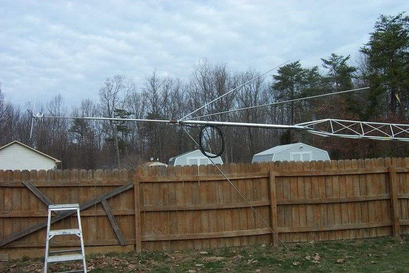
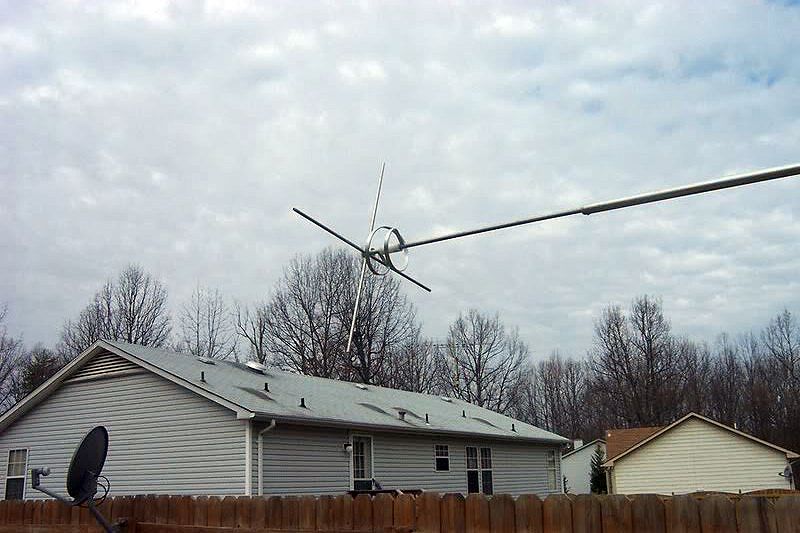
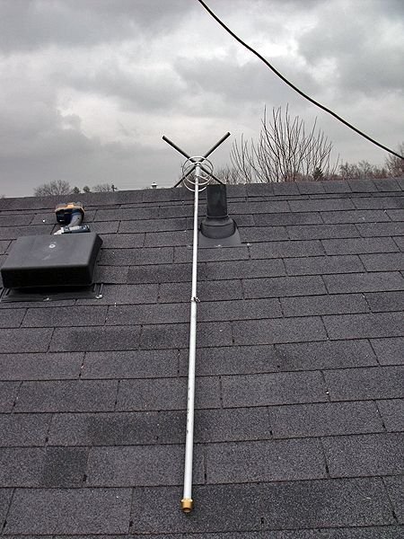
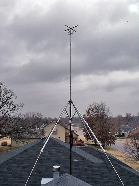
As you can see in the photos it was growing dark quickly here this afternoon due to overcast skies. I put it in the air

with a few things to do. At this point it showed some promise in terms of dialing in the SWR.

Channel 1 is a 1.0:1, and Channel 40 is at 1.1:1. From what I've read the antenna length above the insulator should be

around 72" - 73" tuned for center of CB band. Mine is 75" long, yet it is reading an acceptable SWR. It grew too late and

my day started at 3:00 AM this morning. Ill get back to it as soon as I can.

F0016.jpg


F0017.jpg
F0023.jpg


F0026.jpg
F0029.jpg


I was able to talk to three locals today. A base station 2 miles east, and base station 10 miles west, and a mobile traveling away from me 15 miles out to about 18 miles with great signals and audio into my receive. There has been no DX activity this afternoon, and that was all the local activity. This evening was a bad one for noise in the air, and the antenna was typical of the normal 1/4ƛ GP in terms of noise. Switching off to the horizontal Moxon resulted in a significant reduction in noise.
 
  • Like
Reactions: 4 people

Something you might try when you can, is to increase the distance between coil and capacitive hat. Their proximity, in effect, 'neutralizes' their electrical properties. That's something that has been found a long time ago with 'shortened' mobile antennas.
- 'Doc
 
  • Like
Reactions: 1 person
Yes sir, Doc. I'm with you.
First I wanted to build it as it is and work it at this design to get a feel for it. After that I was intending to try to work on a variance to the design such as you suggest.
You are on target and a little ahead of me.
 
looks good homer. just curious if its mount directly on the pipe [like a starduster]
or clamped on the side?pics look like its bolted directly on the pipe
 
A member of an EU forum said he had not seen a Merlin, so I offered him a summary of the purpose of my build. I wanted to answer the question once for all for myself and any who cared to see my experiment.
Homer said:
Crusty, it is a controversial design over here. It is loved by and sworn upon by those who use it, but vilified by those who think it a flawed design.
Typically placing an Inductor (coil) immediately against a Cap Hat results in the two components cancelling out the work each of them are by nature of design supposed to do. The camp that disbelieves in the antenna say the stuff on the top is essentially eye candy, and a truer more efficient antenna would be a straight shaft 1/4 wave groundplane, or just dump the coil and use the Capacitor Hat if height is an issue. Those who believe the antenna to outperform everything else they've used think it is special and misunderstood, and refute it to be a variant of the simple 1/4 wave groundplane, but is some special concoction of a 1/2 wave.
The second idea (of the 1/4GP being a 1/2 Dipole)presents itself too commonly with the common 1/4 wave groundplane like the Starduster to not think it would be used in the argument in favor of this antenna. Personally I have an opinion on the antenna, but refrain from expressing it until I run it to see what I think is in play.

Original Merlin for comparison to my Homebrew:

55merlin1.jpg


55merlin3-1.jpg
 
Last edited:
Homer here is an overlay of several models I made.


1. is my Merlin 36' 3 radials TH"
2. is with a full 1/4 wave radiator.
3. is with no coil just a Top Hat

*Primary is the Merlin with Low Angle TH no coil and shows the best gain and is about the same as my Starduster model set to specs.

The other three are all about the same...following the same pattern.

View attachment Merlin overlay.pdf
 
Marconi,
Your overlays are very interesting because they indicate that the claim for the Merlin for the superiority of the antenna may be unsuppoerted and cast into some doubt if it shows no better than any other 1/4 wave GP, and slightly less than the 1/4 wave GP with the coil removed.
With the coil removed is the best and indicates the possibility that the advantage of gain and TOA to horizon advantage is lost that is claimed by combining the two devices - coil and CH - so closely.
 
Last edited:
Marconi,
Your overlays are very interesting because they indicate the claim for the Merlin in the above posted claim for the superiority of the antenna is cast into some doubt if it shows no better than any other 1/4 wave GP, and slightly less than the 1/4 wave GP with the coil removed.
With the coil removed is the best and indicates the possibility that the advantage of gain and TOA to horizon advantage is lost that is claimed by combining the two devices - coil and CH - so closely.

Homer, look at the overlay again, there are three models to compare and they all show the same pattern, same gain, and same angle.

The model that shows to be the best model was done by lowering the angle of the radials to about 20* degrees from 40* degrees. I just threw the "Merlin Low Angle TH no coil" model in to show you how you might modify your antenna to show slightly more gain.

There are four models noted, and I added notes hoping to avoid any confusion. The other three models are the ones I compared using the original Merlin model and that was my primary focus.

I'll be posting the models soon, but I hope this explanation clears up what you are seeing in error. For now, just forget about the "Merlin Low Angle TH no coil" model. It is not a part of the 3 antennas in comparison.

I posted more about this on the other forum, if that helps. I should have just done a ditto of the post on Charlie Tango. Sorry for the confusion.
 
Okay. I appreciate the models.
My antenna will get a lowering of the angles simply because mine are a little too far up for a match to the Merlin.
Even your 3 antenna overlays still shows the claim for the Merlin being superior to other antennas of its type to be unsupported. They appear virtually identical.

I will continue to approach the subject as I started for the sake of adding the weight of my own experiences to any conclusions I come to.
 
Last edited:
  • Like
Reactions: 1 person
This is a Merlin project that shows very little difference due to changes in configuration that Homer expects to consider in modifying his real antenna. This suggest to me that the location of the coil being close to the antenna does not present a worsening affect on the pattern, gain, or angle.

The advantage that Merlin describes comes when the top of the antennas are all at the same height.

Their manual states:
"The feed point is 75" inches from the top of the antenna, allowing you to install the antenna in restricted areas with the feed point at the highest possible point."

This is the same type of claim that Avanti made for their AstroPlane.

I have checked the dimensions as close as I can to make sure all dimensions and settings are equal from model to model.

I decided to present this Merlin idea in three files.


View attachment Merlin 36' full .25w model.pdf

This model is the Merlin with a full 1/4 wave radiator at 36' feet to the hub.

The tip of the antenna is noted at 535" when tuned for best match at 27.205. This tip height will be used later to compare all antennas like the antenna maker suggest in his claim. See manual previously posted by Booty Monster.

Note the SWR bandwidth = 3.0 mhz <2.0:1 SWR.

View attachment Merlin 36' radials TH.pdf

1st model is the stock Merlin with top hat and coil at 36' feet to the hub.

2nd model is the stock Merlin raised up 24" to reach the same tip height as the full 1/4 wave model at 535" to the tip.

Note the SWR bandwidths for both are the same at 2.8 mhz <2.1:1 SWR and is reduced a little from the full 1/4 wave model.

View attachment Mer;in 36' 3 radials TH no coil.pdf

1st model is the Merlin with a top hat and without a coil at 36' feet to the hub.

2nd model is the 1st model raised up 17" to reach the same tip height as the full 1/4 wave model at 535" to the tip.

Note the SWR bandwidths are the same for both at 3.0 mhz at <2.0:1 SWR and are back to equal with the full 1/4 wave model.

IMO, this is some evidence that the manufacture is right to make the claim he makes, and the link with the theory described is also correct...except for the very small difference that is noted, which I consider a meaningless difference.

Based on my modeling I consider CBBS is live and well.
 
Last edited:
Okay. I appreciate the models.
My antenna will get a lowering ot the angles simply because mine are a little too far up for a match to the Merlin.
Even your 3 antenna overlays still shows the claim for the Merlin being superior to other antennas of its type to be unsupported. They appear virtually identical.

I will continue to approach the subject as I started for the sake of adding the weight of my own experiences to any conclusions I come to.

That's fair Homer. I see them identical also until I raise the antennas up like Merlin suggested. I'm not trying to change your mind, we each have to do that ourselves...based on our own experiences. Did I steer you wrong on the AstroPlane idea I tried to convince you about before you got yours off that old building?

Regarding the theory, I think this proves to me that the coil close to the top hat does not produce any ill affects in the modeling at least.

Regarding the claim that Merlin published: If you think about the Merlin getting all the antennas at the same tip height then you may see this issue a little differently, just like the eham guys are suggested to BM.

I hope the models I just posted lets you see the difference a few inches can make, and therein lies the snake oil that manufactures and talking heads all use to justify their point. They say it makes a difference, and I say the difference is meaningless. Believe me, I'm not trying to support the Merlin, I think my model shows that the SD'r is still a bit better, but I have not studied why yet. My best guess is that it has radials that are slanted down more, and that is why I put the other antenna in the overlay I sent you. Did I make that clear yet?

Of course the results in the real world may be different. We see this every day, but hanging my hat on a theory that I haven't tried to duplicate and prove is a big "IF" with me. I hope you keep us posted.

I tested my A/P with a full 1/4 wave radiator and I was not impressed. It didn't stay up there long even though it look pretty good.

AstroPlane with .25 wave top element.JPG
 

dxChat
Help Users
  • No one is chatting at the moment.
  • @ Wildcat27:
    Hello I have a old school 2950 receives great on all modes and transmits great on AM but no transmit on SSB. Does anyone have any idea?
  • @ ButtFuzz:
    Good evening from Sunny Salem! What’s shaking?
  • dxBot:
    63Sprint has left the room.
  • dxBot:
    kennyjames 0151 has left the room.