have you tried piggy backing 2 mosfets? would you need to have a separate bias resistor for each gate or would the same pot work for both of them? Did you use the Berguest pads that 399 refers to or is there something better out there now?If you plan on doing my Mosfet mod, you can actually change the 56k resistor to a 100k adjustable pot and set the gate voltage to about 3.9-4V, provided you have a way to transfer heat off the Mosfet properly. Last radio I modded I used a different type of insulator between the Mosfet and the chassis it mounts to, so it thermally transferred heat a little better, so I was able to bump up the bias voltage at the gate up to about 4V. Sounds REAL nice on the air. Good luck.
~Cheers~

You are using an out of date browser. It may not display this or other websites correctly.
You should upgrade or use an alternative browser.
You should upgrade or use an alternative browser.
-
You can now help support WorldwideDX when you shop on Amazon at no additional cost to you! Simply follow this Shop on Amazon link first and a portion of any purchase is sent to WorldwideDX to help with site costs.
-
A Winner has been chosen for the 2026 July 4th Retevis RA89R Giveaway! Click Here to see who won!
Im looking for AM swing mod for a TRC-457.
- Thread starter Dave239
- Start date
")
I used the Bergquist sil-pads. Those work nicely for transferring heat.
I have never tried to run dual Mosfets, as neither the power supply in the radio, nor the AM/USB/LSB mode selector switch can handle the extra current draw. It's not recommended that you do that, unless you install a beefier power supply and a mode switch capable of handling more current.
~Cheers~
I have never tried to run dual Mosfets, as neither the power supply in the radio, nor the AM/USB/LSB mode selector switch can handle the extra current draw. It's not recommended that you do that, unless you install a beefier power supply and a mode switch capable of handling more current.
~Cheers~

I bought 2 sheets I just cant spell it so I should have enough lol. what current draw are you getting out of one mosfet?I used the Bergquist sil-pads. Those work nicely for transferring heat.
I have never tried to run dual Mosfets, as neither the power supply in the radio, nor the AM/USB/LSB mode selector switch can handle the extra current draw. It's not recommended that you do that, unless you install a beefier power supply and a mode switch capable of handling more current.
~Cheers~
Never did measure actual current draw, so I honestly can't give you an answer. It's pretty close to a regular bipolar transistor, I'd reckon. I DID have a mode selector switch on a Cobra 142GTL fail tho because of a Mosfet.... I installed a Mosfet on my 142GTL and it was doing about 30W avg on SSB on my Bird 43A meter.... then I lost LSB... AM and USB was good. So I took apart the mode switch, oops.... the LSB set of contacts had arced over and burned out from the current draw. The Mosfet conversion on the D858 chassis won't be as hot as that 142 and the mode selector switch is constructed better on the D858 chassis. My first President Washington I modded with a Mosfet over 6 years ago still works to this day, no issues.
~Cheers~
~Cheers~
well I appreciate all you help on this topic. Your knowledge is well respected in my house. thanks again and I hope to talk again. I'm off to bed now. 73'sNever did measure actual current draw, so I honestly can't give you an answer. It's pretty close to a regular bipolar transistor, I'd reckon. I DID have a mode selector switch on a Cobra 142GTL fail tho because of a Mosfet.... I installed a Mosfet on my 142GTL and it was doing about 30W avg on SSB on my Bird 43A meter.... then I lost LSB... AM and USB was good. So I took apart the mode switch, oops.... the LSB set of contacts had arced over and burned out from the current draw. The Mosfet conversion on the D858 chassis won't be as hot as that 142 and the mode selector switch is constructed better on the D858 chassis. My first President Washington I modded with a Mosfet over 6 years ago still works to this day, no issues.
~Cheers~
Yep, Exit 13, Robb, Somona, Unit 399, loosecannon, and a host of others know their stuff. I would listen closely to what they say!! JMHO. Do what exit 13 suggested and just turn the AM power back until the desired DK is reached. As long as there is some forward swing, you should be just fine. This won't affect SSB, and the power should be able to be turned up on it without issue other then maybe heat.
Get the modulation to 100% and set the DK to 1 watt. You should then see 4 watts pep. This is a proper ratio of power. 1:4. No it won't make the Dosy meter dance. But should produce a clean signal into the amp. And clean in equals clean out. Also by keeping the power low like the way that was suggested will keep the radio happy as well. Let the amp do the work, not the radio. JMHO.
Get the modulation to 100% and set the DK to 1 watt. You should then see 4 watts pep. This is a proper ratio of power. 1:4. No it won't make the Dosy meter dance. But should produce a clean signal into the amp. And clean in equals clean out. Also by keeping the power low like the way that was suggested will keep the radio happy as well. Let the amp do the work, not the radio. JMHO.
If I run an amp of any kind I set the deadkey on the radio at 2W if I use the D858 chassis. It's high enough to provide some good swing, yet low enough so it doesn't stress the amplifier.
Since this board doesn't modify well for a swing mod, 1W deadkey is too low. 2-3W deadkey is the "sweet spot" on this board for maximum swing. So I'd set it at 2W and let it ride.
~Cheers~
Since this board doesn't modify well for a swing mod, 1W deadkey is too low. 2-3W deadkey is the "sweet spot" on this board for maximum swing. So I'd set it at 2W and let it ride.
~Cheers~
Posted this on the CB Tricks forum a while back.
Let's see if it ports to this forum and works okay.
Finally, I got a "round tuit" for the Uniden 858 SSB radio's variable-carrier setup.
Found the pictures we have used for a while now. Still haven't managed to draw up a schematic.
Parts list:
1) TIP120, 120, 122 or equivalent NPN darlington transistor.
1) 220uf 25 Volt radial electrolytic cap to replace C102
1) 10k 1/4W resistor
2) 680 ohm 1/4W resistor
1) 1k potentiometer. Up to 5k resistance value seems to work okay.
First thing to do is remove TR25, the 2SC1419 AM regulator transistor. In this radio TR25 really is JUST a regulator. It's a variable zener-regulated power supply that feeds power into the secondary of the modulation transformer. It has no audio functions, and is not easily adapted to 'swing' like the later Uniden SSB radios that have the 5-pin mike socket. In those radios THERE IS NO MODULATION TRANSFORMER, and the 2SC1419 in a MB8719 radio is in fact the modulator.
NOT SO in the older 858-based SSB radio. That transformer does the actual modulation of the power to the final and driver.
After you remove TR25, YOU MUST replace C102, a 220uf electrolytic that's between TR25 and the modulation transformer. If you don't there could be trouble. Now is the best time to do this.
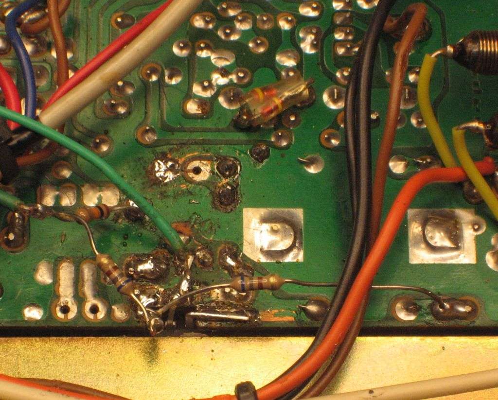
Now install a TIP120 NPN darlington transistor or equivalent in place of TR25. Use the mica insulator and shoulder washer under the screw. Don't forget the heat-conducting compound. You will not connect the base lead of the new darlington. Solder the collector (center lug) and the emitter (nearest the modulation transformer) to the pads where TR25 was connected, but NOT the base leg. Leave it standing up so it won't touch the foil trace where the old 2SC1419 was connected.
As seen in the pics, the two green wires go to your carrier control. The circuit works with the 1k control marked "dimmer" on the front of a RatShack TRC457. Any value up to 5k works okay. You only need two wires, one to the center (wiper) lug and one to the clockwise lug.
One of these wires wil go to the collector lead of the darlington.
Take one of the 680 ohm resistors, and solder one end to the OUTPUT side of the modulation transformer secondary. This is the transformer solder pad farthest from TR25, NOT the one that connects to TR25's emitter lead.
The other end of this 680-ohm resistor now goes to the base lead of the darlington at TR25. ALSO solder one end of the OTHER 680-ohm resistor to the base lead of the darlington TR25. Yes, this looks a bit flaky/shaky but it's a base station, right? It will be sufficiently secure if you solder it securely.
Now take one end of the 10k resistor, shorten it and solder to a handy adjacent ground foil. The free end of this resistor gets soldered to the free end of the second 680-ohm resistor.
The OTHER wire to your carrier control goes to this junction point, where the free end of the 10k and the second 680-ohm resistor meet.
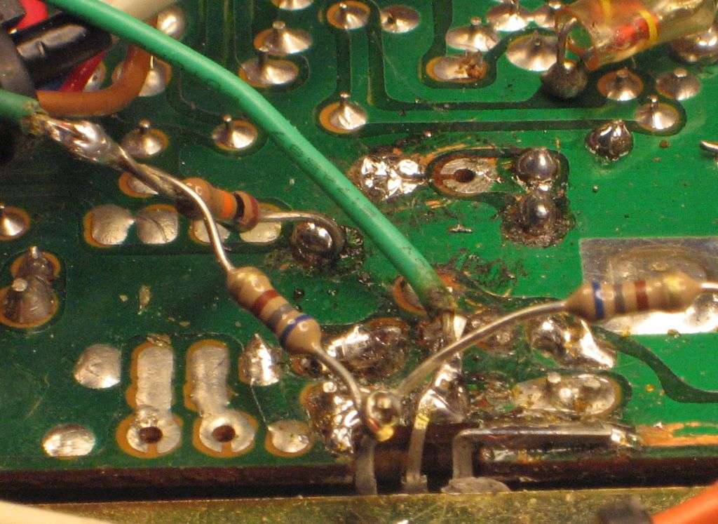
Looks all wrong, but it works. It's very similar to the GE Superbase setup, but not exactly the same.
Yeah, I should draw up a schematic.
Soon.
73
Let's see if it ports to this forum and works okay.
Finally, I got a "round tuit" for the Uniden 858 SSB radio's variable-carrier setup.
Found the pictures we have used for a while now. Still haven't managed to draw up a schematic.
Parts list:
1) TIP120, 120, 122 or equivalent NPN darlington transistor.
1) 220uf 25 Volt radial electrolytic cap to replace C102
1) 10k 1/4W resistor
2) 680 ohm 1/4W resistor
1) 1k potentiometer. Up to 5k resistance value seems to work okay.
First thing to do is remove TR25, the 2SC1419 AM regulator transistor. In this radio TR25 really is JUST a regulator. It's a variable zener-regulated power supply that feeds power into the secondary of the modulation transformer. It has no audio functions, and is not easily adapted to 'swing' like the later Uniden SSB radios that have the 5-pin mike socket. In those radios THERE IS NO MODULATION TRANSFORMER, and the 2SC1419 in a MB8719 radio is in fact the modulator.
NOT SO in the older 858-based SSB radio. That transformer does the actual modulation of the power to the final and driver.
After you remove TR25, YOU MUST replace C102, a 220uf electrolytic that's between TR25 and the modulation transformer. If you don't there could be trouble. Now is the best time to do this.
Now install a TIP120 NPN darlington transistor or equivalent in place of TR25. Use the mica insulator and shoulder washer under the screw. Don't forget the heat-conducting compound. You will not connect the base lead of the new darlington. Solder the collector (center lug) and the emitter (nearest the modulation transformer) to the pads where TR25 was connected, but NOT the base leg. Leave it standing up so it won't touch the foil trace where the old 2SC1419 was connected.
As seen in the pics, the two green wires go to your carrier control. The circuit works with the 1k control marked "dimmer" on the front of a RatShack TRC457. Any value up to 5k works okay. You only need two wires, one to the center (wiper) lug and one to the clockwise lug.
One of these wires wil go to the collector lead of the darlington.
Take one of the 680 ohm resistors, and solder one end to the OUTPUT side of the modulation transformer secondary. This is the transformer solder pad farthest from TR25, NOT the one that connects to TR25's emitter lead.
The other end of this 680-ohm resistor now goes to the base lead of the darlington at TR25. ALSO solder one end of the OTHER 680-ohm resistor to the base lead of the darlington TR25. Yes, this looks a bit flaky/shaky but it's a base station, right? It will be sufficiently secure if you solder it securely.
Now take one end of the 10k resistor, shorten it and solder to a handy adjacent ground foil. The free end of this resistor gets soldered to the free end of the second 680-ohm resistor.
The OTHER wire to your carrier control goes to this junction point, where the free end of the 10k and the second 680-ohm resistor meet.
Looks all wrong, but it works. It's very similar to the GE Superbase setup, but not exactly the same.
Yeah, I should draw up a schematic.
Soon.
73
thanks for all the input. I will have to try this out on one of my units.Posted this on the CB Tricks forum a while back.
Let's see if it ports to this forum and works okay.
Finally, I got a "round tuit" for the Uniden 858 SSB radio's variable-carrier setup.
Found the pictures we have used for a while now. Still haven't managed to draw up a schematic.
Parts list:
1) TIP120, 120, 122 or equivalent NPN darlington transistor.
1) 220uf 25 Volt radial electrolytic cap to replace C102
1) 10k 1/4W resistor
2) 680 ohm 1/4W resistor
1) 1k potentiometer. Up to 5k resistance value seems to work okay.
First thing to do is remove TR25, the 2SC1419 AM regulator transistor. In this radio TR25 really is JUST a regulator. It's a variable zener-regulated power supply that feeds power into the secondary of the modulation transformer. It has no audio functions, and is not easily adapted to 'swing' like the later Uniden SSB radios that have the 5-pin mike socket. In those radios THERE IS NO MODULATION TRANSFORMER, and the 2SC1419 in a MB8719 radio is in fact the modulator.
NOT SO in the older 858-based SSB radio. That transformer does the actual modulation of the power to the final and driver.
After you remove TR25, YOU MUST replace C102, a 220uf electrolytic that's between TR25 and the modulation transformer. If you don't there could be trouble. Now is the best time to do this.
Now install a TIP120 NPN darlington transistor or equivalent in place of TR25. Use the mica insulator and shoulder washer under the screw. Don't forget the heat-conducting compound. You will not connect the base lead of the new darlington. Solder the collector (center lug) and the emitter (nearest the modulation transformer) to the pads where TR25 was connected, but NOT the base leg. Leave it standing up so it won't touch the foil trace where the old 2SC1419 was connected.
As seen in the pics, the two green wires go to your carrier control. The circuit works with the 1k control marked "dimmer" on the front of a RatShack TRC457. Any value up to 5k works okay. You only need two wires, one to the center (wiper) lug and one to the clockwise lug.
One of these wires wil go to the collector lead of the darlington.
Take one of the 680 ohm resistors, and solder one end to the OUTPUT side of the modulation transformer secondary. This is the transformer solder pad farthest from TR25, NOT the one that connects to TR25's emitter lead.
The other end of this 680-ohm resistor now goes to the base lead of the darlington at TR25. ALSO solder one end of the OTHER 680-ohm resistor to the base lead of the darlington TR25. Yes, this looks a bit flaky/shaky but it's a base station, right? It will be sufficiently secure if you solder it securely.
Now take one end of the 10k resistor, shorten it and solder to a handy adjacent ground foil. The free end of this resistor gets soldered to the free end of the second 680-ohm resistor.
The OTHER wire to your carrier control goes to this junction point, where the free end of the 10k and the second 680-ohm resistor meet.
Looks all wrong, but it works. It's very similar to the GE Superbase setup, but not exactly the same.
Yeah, I should draw up a schematic.
Soon.
73
Does the TRC-457 use a pair of transistors for audio amp instead of flat pack IC? If so do not do a swing mod....Set it for 2 watts swinging to 8 or if it will do it 3 swinging to 12 on am and be done with it. If you need more power get an amplifier. Get modulation as close as you can to 100%. If it has never been recapped now is a good time to do it. Check to see if the important transistors are kind of gray instead of a deep graphite black color if so it has either gotten hot, seen lots of use or is just older than dust and might need to have those transistors replaced. Normally voltage regulator's do not age well have no idea why that is. When the SSB finally goes if a general radio recap does not bring and old SSB radio back to life it is normally the cap inside the crystal filter which is a pain the but to replace but it can be done even if excapulated in epoxy! You can prob. get over 300 channels out of that depending ont he rest of the design. The uPD858 in an AM only unit will normaly mod out for more channels than SSB untis but it is still a fantastic PLL to play around with. Just be careful because those do not grow on tree's the PLL that is.
on your mosfet mod on 399's page, you have the 56K resistor as a 1/2 watt resistor, will the 100k pot be just for finding the right resistance to get the 3.9 - 4 V bias then sub in a 1/2 watt resistor close to that value? just not sure what the wattage rating is on a pot.If you plan on doing my Mosfet mod, you can actually change the 56k resistor to a 100k adjustable pot and set the gate voltage to about 3.9-4V, provided you have a way to transfer heat off the Mosfet properly. Last radio I modded I used a different type of insulator between the Mosfet and the chassis it mounts to, so it thermally transferred heat a little better, so I was able to bump up the bias voltage at the gate up to about 4V. Sounds REAL nice on the air. Good luck.
~Cheers~
A standard PCB mount trimmer pot would work fine in place of the 1/2 watt resistor, as the primary current draw is at the Drain on the mosfet. If you want to use the pot to dial it in and leave it in, you can. I just prefer a fixed 1/2 watt resistor to prevent any voltage "float" that can possibly occur from using a variable pot once the gate bias voltage has been set.
~Cheers~
~Cheers~
dxChat
- No one is chatting at the moment.