Yeah, I know ... that's by design. Its a link back to my website and is intended for newer, high resolution monitors. Looks like a computer monitor upgrade is in the future for you as well.Klondike, could you resize your pic? That thing's a monster.

You are using an out of date browser. It may not display this or other websites correctly.
You should upgrade or use an alternative browser.
You should upgrade or use an alternative browser.
-
You can now help support WorldwideDX when you shop on Amazon at no additional cost to you! Simply follow this Shop on Amazon link first and a portion of any purchase is sent to WorldwideDX to help with site costs.
-
A Winner has been chosen for the 2026 July 4th Retevis RA89R Giveaway! Click Here to see who won!
IMAX 2000 ?
- Thread starter IDIeselman
- Start date
Since the Imax and the A99 both count on having a mast beneath them for the counterpoise, and he has isolated it from the mast, I believe it's still hungry for that full 1/4 wave snack.
It seems that full size 1/4 wave ground radials drop the TOA and flatten the pattern and that's why I suggested he add even one 102" whip to the radial hub and test to that same station with that radial pointed in his direction, unless he has 4 102", then do all 4.
Could make for more interesting information to input into the equation.
Since the Imax and the A99 both count on having a mast beneath them for the counterpoise, and he has isolated it from the mast, I believe it's still hungry for that full 1/4 wave snack.
It seems that full size 1/4 wave ground radials drop the TOA and flatten the pattern and that's why I suggested he add even one 102" whip to the radial hub and test to that same station with that radial pointed in his direction, unless he has 4 102", then do all 4.
Could make for more interesting information to input into the equation.
True about the need for a counterpoise/ground plane. Thought he had one on it. The stock Imax counterpoise ground plane kit/four radials are 6 ft long - each. If there isn't any ground plane kit attached and the Imax has been isolated from the mast; then it will have to use the shield of the coax as a counterpoise. Not so great to do it that way, as this will skew the radiation pattern. If no ground plane kit is to be used, then he can also run it w/o isolation and let the mast act as a counterpoise/ground plane. That is how I run mine - BTW . . .
The only reason I can figure for why the ground radial kit, like the one he's using, is only 6' per radial, or a 1/4 wave for 40mhz, is because it just skirts oversize shipping. 
Too bad they don't offer two-piece 9' radials so they would be a full 1/4 wave and then need only a 54" long shipping container.
Too bad they don't offer two-piece 9' radials so they would be a full 1/4 wave and then need only a 54" long shipping container.
These kind of antennas DON'T count on having a metal mast under them, but they do count on having a feed line connected to them which serves the purpose you contribute to the mast.
Those radials on a typical groundplane kit are more 'line isolators' than anything. They aren't of any particular use as a counterpoise, they just aren't resonant in the right frequency range.
Looking for definite, always true reasons for why a particular antenna 'works' better (for whatever reason) is a lot of wasted time when it get's to this point. You have to consider everything around that antenna as contributing to how it works, and that isn't going to be easy or simple. There'll always be something that you didn't account for.
- 'Doc
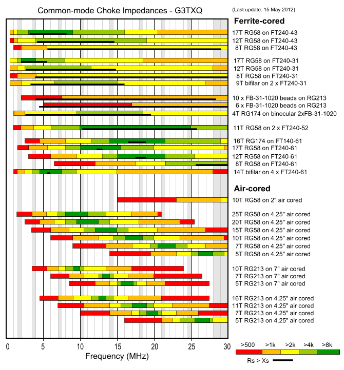
5 turns of .405" diameter coax on 8" former won't give very high choking impedance @27mhz, lmr400 probably won't like been wound on a 4.25" former,
Common-mode chokes
Common-mode chokes
5 turns of .405" diameter coax on 8" former won't give very high choking impedance @27mhz, lmr400 probably won't like been wound on a 4.25" former,
Common-mode chokes
According to the chart you posted, a 5 turn/7 inch air core choke with RG-213 ('RG-8' dia) coax produces only >500 ohms resistance to common-mode current. That isn't enough resistance. So, you are quite right.
When using a 4.25 inch air coil choke form with either RG-8 or RG-58 coax using 5 turns, it will produce >5k ohms of resistance to common-mode current. That would be enough and useful for common-mode current issues.
Thanks for the reminder, Bob . . .
B
BOOTY MONSTER
Guest
well my sirio 2016 i can talk to a local here in his mobile on his way to work
good for bout 40-50 miles.and mine isnt up high at all and has short radials
good for bout 40-50 miles.and mine isnt up high at all and has short radials
so with 213 on a 7 inch former what would be the proper number of turns ? 1 or 2 ? ???
Hard to say. One would think that with the loss of too many winds it would stop acting as a coil altogether.
If I have to do a choke in the future, think I will use a 4.25 inch former and wind it with 5 turns of RG-58 and use a female barrel connector to connect it to my RG-8/RG-213.
Thanks again guys. It appears the majority run the 2000's as they are designed to be ran (not isolated) When it warms up to 28* monday, I will head up that tower one more time to remove all the isolation material and my not so functioning ugly balun, I would have went tighter on the coil/balun but didn't dare with the 400. I have a fairly good baseline of performance and should be able to see if removing the isolation will make a difference. If it does not I will admit defeat and try again following the manufactures instructions with a different antenna (shortly after the brutal destruction of an Imax 2000)
Last edited:
Something to think about.
Over time I've used chokes that I've made that I know to work on some of my antennas. Sometimes they work and sometimes they don't, and that caused me to be curious as to why that was so.
Based on installing my chokes very close to the feed point, why would a choke work well enough to be noticed in one setup, and not work in another...even on the same antenna? The only test results I had available was seeing feed line currents with TVI potentials, and/or not seeing such currents, while using a Field Strength Meter and/or experiencing local interference on some electrical device at my station.
Now, I understand from modeling that, among other things, these currents have something to do with height, maybe just like feed point impedance does. I've also read W8JI's report on the Imax where he discusses this and uses the term "...worst case scenario," in describing an Imax model he tested for his report. IMO, this has to suggest something related to height as well, and this suggest something very similar to what I saw years ago testing my A99 while raising it 1' foot at a time, even using an in line meter. This was the genesis of my idea on TVI related to antennas height or feed line length.
Of course later on I saw the same thing using my Autek VA1 analyzer, and that convinces me that the production of Common Mode Currents (CMC) on the mast and feed line is related to the height above ground, and if you have bad TVI, you could be a foot or two higher or lower from not seeing the problem.
Bob85 and I discussed this idea before, but he was not convinced that is what W8JI was suggesting like I was, so I could be wrong. I wish I was able to physically test this again, but I doubt I ever will. If true, it might help explain why we see good and bad reports all over the map regarding the anecdotal use of coax chokes.
End-fed Vertical and J-pole
Ground Plane Verticals
With all this said however, I've never been able to sense, measure, or determine whether an antenna, showing lots of TVI (presumed to be due to CMC), was any more or less able to TX/RX a good signal...compared to the same or any other antenna I have.
Thanks again guy. It appears the majority run the 2000's as they are designed to be ran (not isolated) When it warms up to 28* monday, I will head up that tower one more time to remove all the isolation material and my not so functioning ugly balun, I would have went tighter on the coil/balun but didn't dare with the 400. I have a fairly good baseline of performance and should be able to see if removing the isolation will make a difference. If it does not I will admit defeat and try again following the manufactures instructions with a different antenna (shortly after the brutal destruction of an Imax 2000)
IDI, I don't think that isolation is your problem. Using LMR 400 for a choke could be an issue however. Before you pull a bone headed stunt and destroy the Imax, check the feed line with the choke in line connected to a good dummy load, connected to your radio, and place an in line meter at the dummy load end to determine RF through put, unless you have a dummy load with an RF meter. Record your results and compare thruput and output to a similar piece of coax, as well as the coax without the choke...if possible.
Here is my Thru Put list of feed lines I use. My dummy load has an RF meter and it may be a bit stingy on the low end of the watts scale.
View attachment Thru Put for Feed Lines.pdf
In case the antenna is bad, I would test it in several places closer to the Earth and see if it is still seems attenuated.
im not sure what you think i was not convinced of eddie, the electrical length of the mast or feedline and it been connected to ground or not can have a significant effect on common mode current magnitude, we have talked about this when we covered the astroplane.
w8ji suggests this in his worst case scenario grounded 1/2wave mast/feedline, maxwell says the same thing in his should swr change with line length.
w8ji suggests this in his worst case scenario grounded 1/2wave mast/feedline, maxwell says the same thing in his should swr change with line length.
dxChat
- No one is chatting at the moment.