• You can now help support WorldwideDX when you shop on Amazon at no additional cost to you! Simply follow this Shop on Amazon link first and a portion of any purchase is sent to WorldwideDX to help with site costs.

ISO: Maverick 250 pics, underside

ExitThirteen

Grumpy and Cranky
Apr 18, 2008
1,968
1,678
173
Cornpatch of Iowa
I know this is (technically) the wrong area to ask, but it IS an amp..

I'm needing a couple of good, clear pictures of a D&A Maverick 250 on the underside of the linear. I have a Maverick here that won't function on SSB. Someone had played around extensively with the keying circuit (it uses a tube for keying, 6AQ5) and now it won't key up at all on SSB. AM works, but it drops out after a few seconds. The 6AQ5 tube checked fine on my tube tester. The one I have is a dual power version. Any pictures and/or help would be greatly appreciated, thanks!


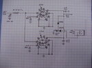
FYI, the schematics on the 'net that I have found do not match what I have.


~Cheers~
 

Thanks Robb, but not what I am after, the schematics at CBTricks do not match. The first one is drawn incorrectly, and the 2nd one is for the original single power version. The keying circuits on both schematics don't match what I have. That's why I made mention that what I was finding on the 'net wasn't matching.


~Cheers~
 
Yep, looks just like that one! I have determined that it's something to do with the capacitor that's used for the delay. However, I don't know what value it needs to be. It's looking like a 10 uF at 150VDC, but I want confirmation of this.


~Cheers~
 
My phantom has that value aluminum can electro cap there. Goes from pin 5 of the 6AQ5A socket, to the SSB switch. Mine blew up, lol.
 
Old post but in case anyone else finds this. I ran across one with a part manufacture defect. The SSB switch was backwards. I learned this inadvertently after recapping one and upon turning it on I noted on SSB the relay was going nuts and on AM the receive kept dropping out. SSB is shown on the bottom, which would make the switch in the on position. I removed the switch to check proper function and on the factory switches there is a on and off plate with a notch that aligns with the detent of the switch. These switches are assembled with two pop rivets. The plate was mounted upside down from the parts manufacturer. What amazed me was this amp is new to me but this one has definitely been around the block and never anyone changed the switch. Hope this helps someone. 73s
 
Yep, looks just like that one! I have determined that it's something to do with the capacitor that's used for the delay. However, I don't know what value it needs to be. It's looking like a 10 uF at 150VDC, but I want confirmation of this.


~Cheers~
I have two of these amps and that capacitor seems to be funny.. one amp has a 10/150 like this (I fixed it from your post) but the other has a 10/450 cap in the same place. Tested a 10/150 and it just locked the relay on. Honestly not a one of these Mavericks seem to be exactly the same.
 
A word of advice. Attempting to actually use the Maverick on sideband will usually result in smoke, and tears.

The driver tubes have no fixed bias voltage. The grids are directly grounded. The radio's carrier serves to turn off the driver tubes ever so briefly during a part of the RF carrier waveform. This reduces current in the driver tubes to a safe level. And it saved D&A the expense of a negative bias circuit like the one that prevents the final tubes from overheating. The final tubes have negative grid bias installed.

The result of this is that the driver tubes will draw more current with the zero drive sideband gets between syllables and words. Most of the time, the driver tubes will "cherry" and eventually break down. When they do the plate choke turns to smoke.

Feel free to experiment with sideband. Might want to keep an eyeball on the driver tubes while you do. The plates are supposed to remain gray. Glowing dull red or orange is just, plain suicidal for those tubes.

But hey, the suicidal tendency on sideband is just a bonus. The unpredictable behavior of a tube-type keying circuit is mostly the fault of using a tube as an on/off switch. It has a tendency to drift into the in-between territory. Turns on but won't always turn off.

Extensive (expensive) modifications can make the Maverick safe for sideband, and smooth out the relay behavior.

The way the factory delivered it, not so much.

73
 
Hello Nomadradio: What voltages are needed to bias the driver tubes do you think?

Thanks for any help here.

Jay in the Great Mojave Desert
 
Hello Nomadradio: What voltages are needed to bias the driver tubes do you think?

Thanks for any help here.

Jay in the Great Mojave Desert
I just take a diode and a filter cap to get a half-wave rectifier from the 6.3-Volt AC heater supply. Gets us about negative 8 Volts DC on the grids. Somewhere here is a post that showed the isolation diode we put between the 1k 5W grid-return resistor and the filter cap. I use 1N5408 because we keep them handy. A 1000uf filter seems to be plenty.

This "two diode" trick prevents rectified "grid-leak" voltage on the tube grids from charging up the filter cap to a higher voltage than the steady 8 Volts.

Naturally, when you unsolder two grid pins from where they were grounded, a .01uf disc cap should always go from the now-loose socket pin to ground.

Gotta find that post.

73
https://www.worldwidedx.com/threads/d-a-warrior-1000.21865/#post-47033 ??
 
Hello Nomadradio: What voltages are needed to bias the driver tubes do you think?

I just ran across this drawing on my computer I did when making modifications to my Hygain 482. Not the same amplifier as the Maverick but a very similar arrangement as @nomadradio mentioned above. I believe this applied about -7.5 v to the grids.
It might help or just delete.

73
David
 

Attachments

  • DSCI0226.JPG
    DSCI0226.JPG
    115.7 KB · Views: 154

dxChat
Help Users
  • No one is chatting at the moment.
  • @ Wildcat27:
    Hello I have a old school 2950 receives great on all modes and transmits great on AM but no transmit on SSB. Does anyone have any idea?
  • @ ButtFuzz:
    Good evening from Sunny Salem! What’s shaking?
  • dxBot:
    63Sprint has left the room.