• You can now help support WorldwideDX when you shop on Amazon at no additional cost to you! Simply follow this Shop on Amazon link first and a portion of any purchase is sent to WorldwideDX to help with site costs.

Lightening L2 Quad

Thank you for the welcome and thank you Marconi for responding. I read all of your previous postings about this antenna as well as other postings. I am glad that you are following along with the project.
The claimed front to back and front to side rejections seem very high for a small antenna. I have no way of measuring that in the field but if I see some sharp nulls of rejection I will be happy.
Thanks

Local says he has assembled 3 of these over the years. States difficulty with getting SWR below 1.7:1. I'll be waiting for your report.
 
Local says he has assembled 3 of these over the years. States difficulty with getting SWR below 1.7:1. I'll be waiting for your report.
Oh boy. We'll see. I have to set up a test mount but it might be only 15' off the ground to the boom.
Not sure if that will mess up the readings.
 
  • Like
Reactions: Mudfoot
The two L2's are supposed to ship today. My buddy and I discussed the options mentioned on this forum for attaching the spreaders with stainless steel hose clamps after notching the aluminum elements. We are leaning towards that instead of drilling through with nuts and bolts thinking that the hose clamp method would leave better option to adjust the elements later in time if needed.
Not sure what the best method is and it has been 35 years since I put up many moonrakers and it reminds me of the way they attached their elements. But I don't remember if the rakers had one cut across the aluminum or two cross cuts where the clamps will go.
 
Last edited:
  • Like
Reactions: Marconi and Mudfoot
Several delays in shipping. Couldn't be home today and left note asking Fedex to leave even though signature required. They wouldn't so now arriving Monday.
 
3 full days of putting this L2 together and getting it mounted up in the air. I don't know where to begin to describe this project.
I put many Moonrakers and PDL2's up in the day but this is more complicated.

SWR vertical 1.3 SWR horiz 1.5
Trying to get it looking symmetrical was impossible. The fiberglass rods are so long that I don't think it will ever have the same distance from wire to wire as it moves in the wind. The quads bow easily and if I loosen the rods to try and compensate the wires just look more droopy. Maybe this is more so because I had them go with 12 Ga copper wire?

Marconi said this and I agree, and I did this.

QUOTE- "IMO, I would slot the 8 metal supports that go thru the boom by 1" - 2" inches. Use this to support and secure the fiberglass rods using good SS hose clamps, instead of those cheap sheet metal screws on a slant...used to secure the FG rods. If you do this, then make your cuts so they remove the screw holes.

This will also help if you ever have to undo these screws to adjust the wire tension. This also can help prevent the FG rods and the screw holes from being all buggered up, coming loose, and maybe shattering the FGRs...as the antenna is bending and twisting in the wind."

The antenna does work and I get a little gain over the 19' half wave that was in the same location. It is above the house with no nearby obstructions. I am using an ICOM IC 7300 which has a digital S- meter but if it's scale is accurate enough to evaluate rejection #'s or gain #'s I don't know. The specs are for 36DB side and rear rejection. At best according to the ICOM meter was maybe 24 db assuming that an S unit is 6 db.

I marked the fiberglass rods with equal paint increments so when adjusting I could make sure all 4 are equally inside the aluminum rods. I tried for the longest time to get little kinks out of the copper wires but couldn't.
 
Hi Mudfoot. The more I use it the more good things I see. It is windy today and I can see the swr going up and down slightly. Yes the swr's worked out well. 1.2 to 1.3 vertical and about 1.4 horiz.
If you take yours out of storage to erect I can give some suggestions. You can see the droop on the patio during assembly in one of these pictures.
 

Attachments

  • IMG_20200608_142536245.jpg
    IMG_20200608_142536245.jpg
    466.2 KB · Views: 67
  • IMG_20200608_140056171.jpg
    IMG_20200608_140056171.jpg
    428.8 KB · Views: 63
  • IMG_20200608_165313331.jpg
    IMG_20200608_165313331.jpg
    585.3 KB · Views: 64
  • IMG_20200609_092415151_HDR.jpg
    IMG_20200609_092415151_HDR.jpg
    450.7 KB · Views: 127
  • IMG_20200609_092429209.jpg
    IMG_20200609_092429209.jpg
    750.1 KB · Views: 67
  • Like
Reactions: Shadetree Mechanic
Nice, I sure appreciate those pictures. It's the matching networrk that boggles my mind. By chance, do you have any other pics? I have been discussing having my friend assemble it. He's the one that's assembled 3 of them over the years. I have a 3 element sitting in the yard. It's all tuned and ready to go. It's set for flatside, but I am want vertical if possible. The L2 will give me both, though.
 
I am enjoying have V and H again. I will attach some more pics. Again this thing is not easy to assemble. There are so many things that don't go together the way you hope.
One check I made was to measure the distance from one quad wire to it's opposite wire shown in a picture with the tape measure. It was about 9' 7" between them but even though I had the rods inequally, this check measurement varied and that bothered me. I went back to each corner clamp and was sneaking a little wire in different directions till the quad was even when measured. When the white and black wires made their way to the matching network the black wires were longer and I started skewing the plastic squares to try and make things equal. Eventually you can see that I put tape at the end of the black wire stub end to equalize things a little.
 

Attachments

  • IMG_20200609_113406780_HDR.jpg
    IMG_20200609_113406780_HDR.jpg
    315.6 KB · Views: 64
  • IMG_20200609_152845674.jpg
    IMG_20200609_152845674.jpg
    395.7 KB · Views: 62
  • IMG_20200608_161124148_HDR.jpg
    IMG_20200608_161124148_HDR.jpg
    367 KB · Views: 60
  • IMG_20200608_165313331.jpg
    IMG_20200608_165313331.jpg
    585.3 KB · Views: 59
These pictures that were posted here a while ago give a better view of things.
 

Attachments

  • L2 quad 2.JPG
    L2 quad 2.JPG
    173.7 KB · Views: 55
  • L2 quad 3.JPG
    L2 quad 3.JPG
    153.5 KB · Views: 55
  • L2 quad 4.JPG
    L2 quad 4.JPG
    181.1 KB · Views: 52
  • L2 quad.JPG
    L2 quad.JPG
    325.8 KB · Views: 126
  • Like
Reactions: Slowmover
Harlequin, thanks for the pictures.

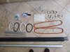
I see the little wire kinks you noted. That might straighten out some over time. I think the original SE manual use to suggest putting some per-tension on the wires before installing.

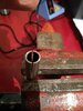
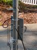
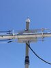
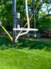
I also see in the image below, where one stub wire (white wire) where it ends...the plastic bracket is twisted a bit. This skewing being in the matching section might ill-effect the match some. In looking at this plastic bracket in the image below, and the way it is secured to the boom, I would be tempted to add more hose clamps to help keep the wire tension and the wind load from inadvertently moving any of these support brackets.

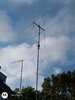
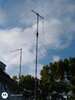
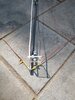
It is hard to really tell the angles from the photo below, but the whole brass rod matching section does not look perfectly square with the mast/boom bracket. If you look down the boom, front to back, these plastic brackets should be perfectly centered and in-line with the boom from the driven elements to the reflector elements, at 3:00 and 6:00. However, I notice the stub wire brackets on the driven end of the boom look perfectly 90* degrees apart.

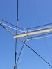
As you can see this matching device is very big and it needs to be well balanced so the matching stub wires are equidistant on both sides of the boom. This is also why the groups of stub wires and brass rods should all be equal to the specs noted for their lengths.

img_20200609_092415151_hdr-jpg.38059


l2-quad-jpg.38075


Just something to consider. This image above of the brass rods also looks a little skewed too.

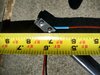
Before you installed everything, did you happen to measure, record, and compare all the like-wire parts to the specs you got in your kit?

Have you sealed the coax exposed ends from the weather and water yet?


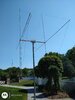
If everything was nice and tight...give your new beam a little time and it may settle down after some time blowing around in the wind, or maybe not...if something was left a little loose and little parts can move around a bit.

Did your kit come with two wires for the radiator, one long (3/4 wavelength) and one short wire (1/4 wavelength)?

How is your buddy coming along with his L2?

Good luck and keep us posted on your progress.
 
Last edited:
Hi Marconi,
I had a situation where the black wires wer longer than the white wires where they reach the connection to the brass stubs. I didn't want to cut that wire of course so I skewed the plastic brackets to try and compensate so the final bends you have to make at the end of the brass stubs would be close to the 3/8" described in the manual. I fiddled with this for some time to try and equalize things out..
I didn't record any wire details but did cross checks with tape measure to have the quads symmetrical.
Yes I sealed the coax connections well after the tuning was done as suggested in the manual.
Yes the driven wires are 1/4 and 3/4 wavelengths.
It is such a balancing act to keep the white and black wires slightly taught as they come down the FG arms. If you get them straight and a little taught you end up bowing the arms. I settled for the white and blacks wires not being straight as I would prefer just to ensure that the quad didn't look bowed. If I could make one change to the design I would make the aluminum tubing longer and the FG rods shorter to be more stable like in the old moonraker. But I don't know if that would change the performance in any way.

My buddy is starting on his today. I pre marked much of the rods with increments so he can make sure they go in and out during adjustments. I wished him better luck getting the copper wires straight where it seems some waviness is unavoidable.

But I am happy to have low swr's and good rejection. The forward gain seems a little better than the omni I had up. Maybe 1/2 to 1 S unit better.

Thank you.
 
  • Like
Reactions: Marconi
Marconi,
This picture might explain why the black wire ends up being longer at the brass stubs.

Also at every clamp holding the plastic insulator, you have to wrap the FB with a decent amount of electrical tape or the clamp won't grip the rods
 

Attachments

  • IMG_20200609_113406780_HDR.jpg
    IMG_20200609_113406780_HDR.jpg
    315.6 KB · Views: 41

dxChat
Help Users
  • No one is chatting at the moment.
  • @ Wildcat27:
    Hello I have a old school 2950 receives great on all modes and transmits great on AM but no transmit on SSB. Does anyone have any idea?
  • @ ButtFuzz:
    Good evening from Sunny Salem! What’s shaking?
  • dxBot:
    63Sprint has left the room.
  • dxBot:
    kennyjames 0151 has left the room.