• You can now help support WorldwideDX when you shop on Amazon at no additional cost to you! Simply follow this Shop on Amazon link first and a portion of any purchase is sent to WorldwideDX to help with site costs.

LIGHTNING ANTENNAS "White Lightning" 4-element quad review

unit_399

EL CAPO
Jun 17, 2008
2,107
2,981
273
ALEJANDRIA, COLOMBIA SA
After a lot of procrastination, I am finally getting my station back on the air. My original plan was to build my own 4 element quad, and mount it on a guada pole like I always have done. But a friend told me of a local ham that was moving to a new home and was selling his antenna system. We discussed pricing and agreed to a price of $2,500,000 Colombian pesos ( about $550 USD).
The system consists of the following:

1 Hygain Explorer 14 Antenna for the 20, 15 and 10 Meter bands
6 Tower sections 3 meters each with their screws
9 steel guy lines for the winds
1 Ham IV Rotor with its table controller in perfect condition
90 meters of coaxial cable LMR400
90 meters of cable 4 pairs for rotor line
I was able to sell the antenna to another local amatuer for $500,000 COP which made the deal even better.

Instead of building my own quad, I bought a Lightning Antennas "White Lightning" 4-element quad. Received the antenna last Friday, unpacked it, and started putting it together. These are my first impressions.

LIKES:
The antenna was very well packed, and arrived here from the US undamaged.

High quality parts.

Everything predrilled so assembly is easy - only basic hand tools needed

Stainless steel hardware

Very good assembly instructions.

DISLIKES:
Hokey driven element and stub matching design. I discarded it and replaced the 2-piece driven element wire with a single wire for horizontal polarization only.

When the factory drilled the element support tubes, they distorted them slightly, so I had to file the holes in the boom so that they would fit. A real PITA.

No dimensions in the spec sheet for element wire lengths, element spacing, etc. So I had to measure everything to establish a baseline in case I wanted to change something. AGAIN, a real PITA.

That pretty much sums it up so far. I'll begin assembly tomorrow, AFTER I finish filing out the 32 element support tube holes in the boom sections.

I'll post assembly and install pics later.
wlunpack.png.
Here's a photo of the antenna after unpacking.
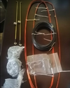
wl stub.png
Unused driven element wires and stub match.

- 399
 
Last edited:

UPDATE:
Finished putting the antenna together yesterday. Just needed to adjust the bottom spreaders to get the wires tight. The element wires are soldered in a loop from the factory and then bent into an oval shape for shipping. Trouble is, it makes stretching the wires to get the bends and kinks out impossible. Makes checking the element lengths impossible too. When I unsoldered the loops and checked the lengths, none of them agreed with any numbers that I got from several quad calculator programs. Some too long, and some too short. I shortened the long ones, and replaced the short ones with wire that I had on hand. When I assembled the wires, I found that the spreaders for the 1st director were too long and bottomed out in their support tubes and had to be cut down a bit to make them work. So "plug and play" assembly is a joke.

After trying to install the element wires using the method shown in the instructions, I gave up in frustration. Trash-canned the instructions and did it my way. I put the completed antenna up (temporarily) on a 20' pole on the top of our garage (38' total). SWR checked out at 1.4:1. Just some fine tuning and it will be ready to go on the tower.

On a scale of 1 to 10, I rate it a 7. Whoever calculated the wire lengths needs help, and I'm certain the person who wrote the assembly instructions NEVER tried to assemble an antenna using them. But, after a lot of extra work, the final result is good.

- 399
4Quad.png
 
UPDATE:
Finished putting the antenna together yesterday. Just needed to adjust the bottom spreaders to get the wires tight. The element wires are soldered in a loop from the factory and then bent into an oval shape for shipping. Trouble is, it makes stretching the wires to get the bends and kinks out impossible. Makes checking the element lengths impossible too. When I unsoldered the loops and checked the lengths, none of them agreed with any numbers that I got from several quad calculator programs. Some too long, and some too short. I shortened the long ones, and replaced the short ones with wire that I had on hand. When I assembled the wires, I found that the spreaders for the 1st director were too long and bottomed out in their support tubes and had to be cut down a bit to make them work. So "plug and play" assembly is a joke.

After trying to install the element wires using the method shown in the instructions, I gave up in frustration. Trash-canned the instructions and did it my way. I put the completed antenna up (temporarily) on a 20' pole on the top of our garage (38' total). SWR checked out at 1.4:1. Just some fine tuning and it will be ready to go on the tower.

On a scale of 1 to 10, I rate it a 7. Whoever calculated the wire lengths needs help, and I'm certain the person who wrote the assembly instructions NEVER tried to assemble an antenna using them. But, after a lot of extra work, the final result is good.

- 399
View attachment 64125
Looks great! Let us know when it's pointed north and we will see if we can connect.
73
Chris
 
  • Like
Reactions: unit_399
Sounds like you basically did build the antenna yourself. Shame you had to do that when you paid good money for it. It'll probably perform better because of your efforts though.

7 3
Thanks Crawdad. Yep, a lot of extra work, but no regrets about the money I spent. The mechanical parts are very good quality, strong, and a nice tight fit. Their mechanical alignment is something I would have struggled to do as well in my home shop.
The next thing is to get the tower /antenna up. I hired a local communications firm to construct everything. I'm too old to be doing this kind of work. They're coming out this week to pour the concrete base and the guy wire anchors. A few days for the concrete to dry, and they'll be back to finish things up. I should be back on-the air by the end of June at the latest. FINALLY !!

- 399
 
I need some information on a lightning antenna call me @ 504 - **6-**** Mark
 
Last edited by a moderator:
Hey Jim, great work!

And lots of it, as it turns out.

Did you use the original "Signal Engineering" feed method? Back in the day they named it the "Signal Feed System", or SFS. Has the coax braid grounded to the boom and the feedline's center conductor feeding into a zig-zag of rods parallel to the boom. The driven element is one unbroken piece of wire and a feed wire from the zig-zag match feeds it as if it were two end-fed half waves in parallel.

I have one that a customer built, with wires for the "zig-zag" rather than solid rods. Folks who copy it call it the spaghetti match.

That antenna did one thing I have never understood. Any time I pointed it at another antenna of the same kind, you couldn't tell a signal difference when you switched polarization. I could select vertical or horizontal and have a hard time seeing a difference. Discovered this when a customer forgot to mark his two coax cables. Wanted me to tell him which was which by watching my S-meter. Couldn't see enough difference to tell him which coax was which.

Only did this pointed at another White Lightning, or similar copy. Pointed at a conventional cubical quad or a dipole Yagi the difference between vertical and horizontal would be multiple S-units.

Never have figured that one out.

Here's hoping it lasts a long while.

73
 
  • Like
Reactions: Shadetree Mechanic

dxChat
Help Users
  • No one is chatting at the moment.
  • @ Wildcat27:
    Hello I have a old school 2950 receives great on all modes and transmits great on AM but no transmit on SSB. Does anyone have any idea?
  • @ ButtFuzz:
    Good evening from Sunny Salem! What’s shaking?
  • dxBot:
    63Sprint has left the room.