• You can now help support WorldwideDX when you shop on Amazon at no additional cost to you! Simply follow this Shop on Amazon link first and a portion of any purchase is sent to WorldwideDX to help with site costs.

Maco 300 pumpkin face 1 driving 4 8950 Problems with red plating and have to constantly retune after one minute of no keying

442FlatFoot

Member
Aug 21, 2022
8
0
11
46
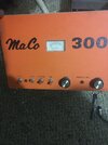
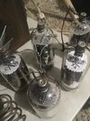
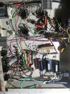
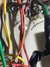
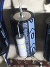
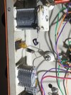
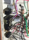
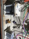
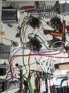
So I traded my brand new old stock varmint XL 600 mobile amplifier for a Meiko 300 plug in the wall well I can’t get no more than 100 W out of this thing PEP and that’s with any radio I use that so far my cobra 29 with a variable dead key with the swing kit And I went through and turned down my striker 955 so I can’t get 100 W with that right now I’m getting just as much power with the app as I do without it two of my tubes are glowing blue the other two are not I just never had a tube amp I’ve always used arm pills If anybody has one of these pumpkin face 300s and have the schematics for it or I can take pictures of the bottom of the inside and everything for me just so I can see if everything’s wired right because by looking at other Maaco amps someone has definitely been in the sand and did some really bad soldering but on top of that the wiring so I think it’s wrong for the heater and stuff I’m just trying to see if everything’s right and you know what I’m gonna need thank you so much guys
 

Attachments

  • 7A7E0712-9C9E-4F7E-A7CC-7D6C0B5A489B.jpeg
    7A7E0712-9C9E-4F7E-A7CC-7D6C0B5A489B.jpeg
    682.8 KB · Views: 62
  • 6324F432-18CE-4E05-81FC-674AE938CD3F.jpeg
    6324F432-18CE-4E05-81FC-674AE938CD3F.jpeg
    755.8 KB · Views: 63
  • 0A8460B4-BEB3-45E7-9873-5027E9AF08D4.jpeg
    0A8460B4-BEB3-45E7-9873-5027E9AF08D4.jpeg
    2 MB · Views: 54
  • A30E2331-0C28-448E-A9BD-88A149C081CE.jpeg
    A30E2331-0C28-448E-A9BD-88A149C081CE.jpeg
    1.1 MB · Views: 58
  • F89D9E28-3526-414E-99BD-4BF921271BE8.jpeg
    F89D9E28-3526-414E-99BD-4BF921271BE8.jpeg
    1 MB · Views: 59
  • D161D787-6507-4C87-98E9-477AFDDC7323.jpeg
    D161D787-6507-4C87-98E9-477AFDDC7323.jpeg
    1.1 MB · Views: 54
  • 4EA9A45C-4EE7-4A99-A11B-CD0FAF5D4D84.jpeg
    4EA9A45C-4EE7-4A99-A11B-CD0FAF5D4D84.jpeg
    1.2 MB · Views: 59
  • 88BAB874-D087-4C5B-A318-7D040A6E7DFE.jpeg
    88BAB874-D087-4C5B-A318-7D040A6E7DFE.jpeg
    1.6 MB · Views: 56
  • AF5E804C-48D5-4250-A31A-801B4AE241F8.jpeg
    AF5E804C-48D5-4250-A31A-801B4AE241F8.jpeg
    1.8 MB · Views: 57

Two things to look at first. The Tune control for the driver on the side, and for the final in front should show peak power with the plates somewhere between the two extremes. If the wattmeter peaks out with the plates fully meshed together, or all the way apart, this is probably part of the picture.

I really should put up a sticky for getting the Tune controls to peak properly inside their end-to-end adjustment range. A Tune control that appears to show a peak when it's all the way at one end is not really peaked, it just fooled the wattmeter. Turning it either way from that one extreme looks like a peak when you're turning the knob.

But it isn't. It's late and I should be in bed already. Have a look at the tuning controls and see if I'm right about the position they're at when they appear to be peaked for max power.

We can take it from there.

73
You are correct the load is about halfway fins are about halfway But the fins on the tuning on the driver is all the way open And the driver section tune is almost all the way open
 
You are correct the load is about halfway fins are about halfway But the fins on the tuning on the driver is all the way open And the driver section tune is almost all the way open
Dang it the final section tune is all the way open and the driver section is almost all the way open
 
Okay, the plates all-the-way-open end of the capacitor is the minimum end. Can't reduce the capacitance of the control any more. To reach proper tuning, you need less. In this case, the only handle you can crank, so to speak, is the coil attached to that Tune control. Since our starting point is "too much", reducing the inductance value of the coil is next. Spreading the turns of the coil farther apart will do this, especially if they are really close together. But if they are already spread apart, a wire soldered across one turn or one-half of a turn will reduce the coil's inductance value. This will now require the circuit to have more capacitance to tune the frequency you are feeding into it. Removing one full turn of the coil may overshoot, and reduce the inductance too much. You'll know this happened when the Tune control now shows its peak at the opposite extreme, with the plates meshed as fully together as they'll go.

This is not so different from the artillery officer getting his barrel elevated correctly to strike his target. If the shot lands far, you raise the barrel. And when the next shot falls short, you lower the barrel half as much as you raised it. This process will "bracket" your target and eventually score a direct hit.

If shorting one full turn overshoots and reduces the coil's inductance value too much, you could squeeze the coil's turns closer together, especially if they are already spread apart. Might bring you into range. If it won't, try shorting across just one-half of a turn.

Some amplifiers will have a tap wire already visible on the coil. Others will not.

There is no universal 'one size fits all' rule for getting this right. Only a procedure, that enough iterations will achieve a peak setting that's near the center of the control's range of motion.

There is an easier way to tell this about a sweep-tube amplifier without removing the cover. Any tuning capacitor that turns a full 360 degrees with no end stop will exhibit TWO peaks in one full turn of the knob. They might be 180 degrees apart. They might be close together. But if you can't see two distinct peaks in one full turn of the knob, you will see this "at one end" setting of the control when you peek inside.

And a tuning capacitor that has an end stop at 180 degrees will tell you right away that it's not reaching a proper peak.

73
 
"Constantly needing retuning after a minute of no keying", sounds like a fixed value capacitor across the tune or load, is shifting in value as it heats. Not even sure if there is one padding that variable, but it is one of the few things that cause that symptom.
 
  • Like
Reactions: Naysayer
An unstable plate-blocking cap can sure do this. Good chance a damaged cap will measure wrong even when cold.

73
I've seen that happen with a few of the old red door knobs that they used in Heath kits. There're not as good as the tan colored ceramic ones. I'm sure they didn't use anything quite as good here either. Not that it's required.
 

dxChat
Help Users
  • No one is chatting at the moment.
  • dxBot:
    Tucker442 has left the room.
  • @ BJ radionut:
    LIVE 10:00 AM EST :cool:
  • @ Charles Edwards:
    I'm looking for factory settings 1 through 59 for a AT 5555 n2 or AT500 M2 I only wrote down half the values feel like a idiot I need help will be appreciated