• You can now help support WorldwideDX when you shop on Amazon at no additional cost to you! Simply follow this Shop on Amazon link first and a portion of any purchase is sent to WorldwideDX to help with site costs.
  • Click here to find out how to win free radios from Retevis!

Magnum S680 29.090mhz only

Hawkeye351

Well-Known Member
Jun 27, 2021
557
453
73
56
Hi all,
I decided to put the connex 3300hp to the side and start on another one til I can rethink the 3300.

Radio - Magnum S-680
Issue - transmits and receives on only 1 frequency regardless of band selected or channel knob location.
Also, no lights or displays.

Radio transmits fine, Deadkeys 10w and swings up to around 60w PEP. Only thing is, it transmits only on 29.090mhz regardless of channel knob position or band selected. Turning channel knob or band selector makes no difference, still always on 29.090mhz.
 

Depending on what year it was made there might be a CPU reset button in there. If not check and see if it is one of the older versions that has con 1,2,3 ports inside with a jumper that plugs in. The options were 10m only, 11m only, and export mode depending on which con port was plugged in. Unfortunately the CPU might be stuck or damaged.
 
  • Like
Reactions: Hawkeye351
Mine looks just like the one pictured as above.

Pin 1 and pin 4 are jumpered (ON state).

Where would I look for the reset button, if it has one?

Also, this radio has no display of any kind. Channel indicator does not light up, frequency counter does not light up and neither does the meter light. When I first turn the power on, the meter light will flicker on then off and stay off until I turn the radio off and back on, then the meter light will flicker on then off again.

I checked the 8v regulator and the small regulator that's against the 8v regulator, the voltages on those are correct.

It's as though half the radio works, while the other part doesn't switch on.

Meter works,
All controls work (except Band, channel and 10khz),
Transmit works

Just stuck on one frequency and has no display at all, no lights.
 
Well, you can't even begin until you reinstate control panel voltages and get the displays working and when you do you may find the radio coming back to life. You may find a bad connection or switch or something but first fix the lights.
 
  • Like
Reactions: Hawkeye351
WARNING, never had one of these, just going by what I see on cbtricks.

It looks like IC101 (CPU) outputs three signals for the display power (pins 35, 30 and 31) which then get buffered via PNP transistors that supply the positive for the displays. The individual segments appear to be grounded via the shift registers, and I doubt that is the issue because all three would have had to fail. That puts the focus on the CPU or the PLL.

It is unlikely for three different CPU outputs to be burnt out, especially being buffered, so if pin 9 of IC101 has 5v (thats the CPU's Vdd, and it not being shorted suggests the CPU is probably ok), I would be leaning towards the PLL being out of lock somehow, but that is just a guess because I have no idea what that CPU does in that condition.

You may be able to trick it for a moment just to see. It appears that the PLL Enable is on pin 38. I do not know if it is supposed to be high or low, but momentarily clipping R112 (on the side away from the CPU) so the state can be changed maually (at the clipped end of the resistor) would provide an opportunity to see if the displays come back on. Don't leave it like that though. I want to think this is a PLL lock issue because having just one output frequency would suggest that the VCO is running at one of its frequency limits ~ driven all the way to one side of its range and holding there.

One thing I do find interesting is that the schematic calls for a 8MHz clock crystal and the datasheet for that CPU lists a max input of 6MHz. Also, the AMF input (pin 4, for the signal from the VCO) has a 10MHz maximum in the datasheet. I do not know what the VCO is supposed to run at (couldn't find that on CBTricks), but I have to wonder if they exceeded the datasheet specs there too.
 
Last edited:
  • Like
Reactions: Hawkeye351
The schematic for the mcu/freq board doesn't match with the board layout correctly.

The schematic shows j104 as the 2 wire input, but the board layout and my mcu/freq board shows j104 on the bottom beside j106. Where the schematic claims j104 is the input, is actually j100 on mine and the board layout.

I checked voltages (primarily input voltage and voltage going to the display board from this board.

All pins are at zero (0) volts except j100, the input voltage, which suppose to be 9v and I'm getting around 8.94v. So, I have input voltage going to the mcu/freq board, but no voltage coming off the mcu/freq board.
 
Last edited:
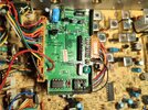
Wow, after zooming in close on the above photo, I can see several bad/open solder joints. Gonna touch those up.

Don't ask me about the hanging nub of a wire at J106. There are no lose/free hanging wires in the radio. I do notice that the trace goes nowhere, so it must not be needed. The schematic calls for that to be ground.
 
  • Like
Reactions: Mudduckmobile
Made a correction on a previous post:

I stated j102 was my 9v input, it's actually j100. That's the one on the bottom left (red/black). It shows a little over 8.9v.

The 9v input from that j100 goes directly through an inductor (L100) first. Well, on the j100 side of that l100 inductor I see the 9v (of course), but on the other side of that l100 inductor all I get is less than half a volt. That inductor looks fine, looks new.
 
The 9v input from that j100 goes directly through an inductor (L100) first. Well, on the j100 side of that l100 inductor I see the 9v (of course), but on the other side of that l100 inductor all I get is less than half a volt. That inductor looks fine, looks new.
Looks can be deceiving, how does it read on an ohmmeter? It may look like a short, but it should never read as open.
 
  • Like
Reactions: Hawkeye351
I had an inductor on a TS440 bite me once. All of the dreaded dots on display. Reworked the PLL board, repaired thousands of solder joints on every board in the unit, and every other suggested repair for the dots on display.
Found an inductor (on the RF board if I remember correctly) bad. Replaced it and the 440 is still going strong.

Just my 2 cents. Good Luck!

73
David
 
  • Like
Reactions: Hawkeye351

dxChat
Help Users
  • No one is chatting at the moment.