• You can now help support WorldwideDX when you shop on Amazon at no additional cost to you! Simply follow this Shop on Amazon link first and a portion of any purchase is sent to WorldwideDX to help with site costs.

Matching Coil

JDemoret

Member
Mar 5, 2009
41
0
16
61
I am fooling around with building a .64 wave vertical and I'm trying to wrap my head around setting up the matching coil. This is in the very rough stages (basically a 22ft. solid 12ga.wire connected to a SO239) and I want to know if I'm getting the basic theory right. I know there will be alot of adjustments and maybe redoing the coil several times.

Thanks in advance
John
 

Attachments

  • antenna 019.jpg
    antenna 019.jpg
    2.2 MB · Views: 30

After thinking about it I made a change. Which is correct?:headbang

Thanks
John
 

Attachments

  • antenna 020.jpg
    antenna 020.jpg
    2.2 MB · Views: 27
John,
They both could be made 'better'/simpler. One end of the coil connected to the antenna at the center of the SO-239, no connection at the top of the coil. A shorting strap for the tap. Basically puts the coil between the (+) and ground, the shorting tap determines how much coil is between (+) and ground. Make sense?

Or...

Bottom of the coil to ground, top of coil connected to the antenna (+). Center conductor of feed line is the tap. You end up with two coils, one feeding the antenna, one going to ground. Combination loading and matching coils.

The first one will work for any 1/4 wave antenna matching. The second for something like a 5/8 wave, or a shortened 1/4 wave, if that makes sense...
- 'Doc
 
Doc,
If I am correct your second suggestion would require knowing the exact diameter and number of turns of the coil to obtain a correct match.

It sounds like your first suggestion would be "adjustable" over the length of the coil which could ultimately lead me to sugestion number 2.

:confused:

yes or no?

Thanks for replying
John


After reading the reply for the fifth time I think I'm still not getting everthing about this coil.
On your second suggestion would I just connect the braid of the feedline to ground with the bottom of the coil and use the center conductor to adjust around the coil? Hate to sound dumb about this and thanks for the help.
 
Last edited:
I copied this info from another location to here for you to read:

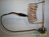
I calculate that you need about 10 turns of #12 wire on a 1 1/2 inch form, spaced out over about 2 3/4 inches.

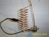
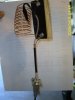
You connect the coil top end to the base of the vertical radiator and coil bottom end to the radials' common point. I know it might sound weird to put a coil *across* the feedpoint, but trust me!

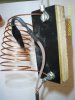
The shield of the coax cable connects to the radial common point/bottom of the coil. Then you take the center conductor on the coax and attach it a *couple turns up* from the bottom of the coil... I think 2 turns up should do it.

|
|
|
|
|
|
|
|
| vert
|
|
|
|
x
x coil (10 turns #12, 1.5 inch form, 2.75 inch long)
x
x
x -- center coax tapped 2 turns from bottom of coil
x
O -- radials and coax shield meet here, coil bottom

It's a nice design because it keeps static from building up on the vertical radiator.

There are two ways you can adjust it.

Spreading and compressing the coil length will change the resonant frequency, and that will be the frequency where you get lowest SWR. If you find the SWR is lowest at the bottom of the band, spread the coil. If lowest at the high end of the band, compress it. You can also trim or lengthen the vertical radiator instead.

If you sweep across the channels and find the lowest SWR is in the middle of the band but it's not very low... like the lowest SWR is 2:1 but it happens on channel 20 or so, adjust the location of the coax center conductor tap on the coil.

You can change the coil a little bit but don't make huge changes... the diameter, number of turns and length should be about right.

Good luck with the project, you'll love the feeling of using your own homemade antenna and having it work well.

My first homemade antenna was a vertical dipole for CB inside some 1 1/2" PVC pipe. I clamped it to the side of the house and it worked really well.

http://www.eham.net/forums/HomeBrew/4665?cookietest=1
 
Thanks Homer, I've read that post several times. I'm going to change it around when I get off work in the morning and post results tommorow sometime.
Thanks for bearing with me and your help. (y)
 
"...would I just connect the braid of the feedline to ground with the bottom of the coil and use the center conductor to adjust around the coil? Hate to sound dumb about this and thanks for the help."
You aren't sounding dumb. My verbal descriptions aren't the best in the world. You've basically got it right though. 'HomerBB's diagram pretty well shows what I was trying to say. The 'tap' point on that coil can be almost anywhere around it, so a few 'contortions' are probably going to happen, some not exactly the best particular way to do it. But, when you get close you can figure out a less 'contorted' route. If it works, who cares?
- 'Doc
 
Well, I made some changes and this is what the final design is per suggestions (see attachments).

Now for the initial tests.... I started with the coil shown (10 turns at 1.5" diameter) taped at the second turn of the coil SWR is up over 3:1. Made several more adjustments in the tap point and compressing and lengthening the coil, the best I got was around 2.5:1.

Changed the coil (10 turns at 2.75" diameter) same kinds of adjustments over the next 30 minutes and the best I got was around 2:1. Changed the coil again (12 turns at .75" diameter) all adjustments yeilded nothing better than 3:1. I double checked the connection to earth (ground) and put 6 turns of coax of about 8" at the feed point to eliminate common mode current.

The main problem I think I'm having is the placement of the antenna. Since it won't stand up on it's own I've had to hang it from the side of the house to get it vertical. None of the antenna is in the "clear" and it is about 2 feet from the house. I'm going to try to get it hoisted up into a tree to see if it gets any better.

If I can get this one to work fairly well I wan't to build the final antenna from alumminum tubing. I think I can still build it for alot less than the Imax 2000. Plus I built it.

So the project continues and any and all suggestions are welcome.

Thanks
John
 

Attachments

  • antenna 022.jpg
    antenna 022.jpg
    2.2 MB · Views: 28
  • antenna 023.jpg
    antenna 023.jpg
    2.2 MB · Views: 23
Am I just missing it, or are there no 'radials', or 'ground', or counterpoise, or whatever, at the bottom of that coil? How about removing that coaxial choke and seeing what happens, forget about the CMC stuff. The antenna being close to the house will make some difference, but it should still be better than what you're seeing I'd think.
- 'Doc
 
Doc,
Those photos were taken in the garage before the antenna went up. There are no radials but the antenna is grounded to a grounding rod in the ground. I put the RF choke on because once I got the best match I could on Ch. 20 I checked it on Ch. 1 and Ch. 40 and it was the same on all 3 channels.

Any and all help will be appreciated.

Thanks
John
 

dxChat
Help Users
  • No one is chatting at the moment.