Trying to get this radio to go down to cover 26.755,Has the PLL02A,I iknow they are differnt from say the Kraco AM only boards..I have tried all i know and i can only get high channels no matter what i do..Can't get it to go down at all..I know there is a way but can't seem to find in onlne.Anyone here have info on this radio?Thanks in advance

You are using an out of date browser. It may not display this or other websites correctly.
You should upgrade or use an alternative browser.
You should upgrade or use an alternative browser.
-
You can now help support WorldwideDX when you shop on Amazon at no additional cost to you! Simply follow this Shop on Amazon link first and a portion of any purchase is sent to WorldwideDX to help with site costs.
-
A Winner has been chosen for the 2026 July 4th Retevis RA89R Giveaway! Click Here to see who won!
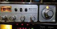
Midland 79-892 Low ch
- Thread starter n4dxx
- Start date
I'll need to dig out Sams CB180 when I get to work. Seems to me this is a 'reverse' PLL radio. The binary codes count down as the frequency goes up. This tends to require that two or three pins of the PLL get their logic state modified to go below channel 1.
Pretty sure taking loose one or more input pins that are soldered to high or low is part of the picture. Pins 8 and 9, pretty sure. It's all about the arithmetic. The Sams has that part of the picture.
73
Pretty sure taking loose one or more input pins that are soldered to high or low is part of the picture. Pins 8 and 9, pretty sure. It's all about the arithmetic. The Sams has that part of the picture.
73

Thanks i'll be on standbyI'll need to dig out Sams CB180 when I get to work. Seems to me this is a 'reverse' PLL radio. The binary codes count down as the frequency goes up. This tends to require that two or three pins of the PLL get their logic state modified to go below channel 1.
Pretty sure taking loose one or more input pins that are soldered to high or low is part of the picture. Pins 8 and 9, pretty sure. It's all about the arithmetic. The Sams has that part of the picture.
73
Here are a couple of links you may have, or not. Information on the O21
If you have them, sorry for the repeats.
This model was my first SSB radio and escalated my radio world. With a Radio Shack 1/2 wave omni and the stock radio I was able to talk the world...in the late 70's early 80's. The clarifier built into the mic was a cool feature.
The Defpom PLL02A, MC145109, MM48414, AN6040, MN6040, SM5109, TC9100 Component Info page
A page with component info for various cb radios
www.radiomods.co.nz
If you have them, sorry for the repeats.
This model was my first SSB radio and escalated my radio world. With a Radio Shack 1/2 wave omni and the stock radio I was able to talk the world...in the late 70's early 80's. The clarifier built into the mic was a cool feature.
Those mods only work on AM only boards as far as i know..ThanksHere are a couple of links you may have, or not. Information on the O21
The Defpom PLL02A, MC145109, MM48414, AN6040, MN6040, SM5109, TC9100 Component Info page
A page with component info for various cb radioswww.radiomods.co.nz
If you have them, sorry for the repeats.
This model was my first SSB radio and escalated my radio world. With a Radio Shack 1/2 wave omni and the stock radio I was able to talk the world...in the late 70's early 80's. The clarifier built into the mic was a cool feature.
Disclaimer: I haven't actually tried this and I have no idea what your soldering skills are. So don't blame me if you fry your radio.
SSB PLL02a chassis. You could try swapping out the loop mixing crystal. 10.0525 Mhz should give you 40 below.
Then there's playing with the PLL programming pins. The N-codes on the SSB chassis go down numerically from channel 1 (N-code 255) to channel 40 (N-code 211). So with that info we can probably figure out what to hack to make this work on 26.755 MHz.
We know what the frequency of channel 1 is, 26.965 MHZ. So let's take the difference between that and where you want to be: 26.965 - 26.755 = 0.21, or twenty one channels below 1. Since you have to count the N-codes up to go lower you would then add 21 to the N-code for channel 1: 255 + 21 = 276.
Which translates to pin 7 high, pin 8 low, pin 9 low, pin 10 low, pin 11 high, pin 12 low, pin 13 high, pin 14 low, pin 15 low.
After writing that I did a goofball search for "pll02a ssb chassis truth chart", and this was the first hit: https://groups.google.com/g/rec.radio.cb/c/_zVUdnc_lv0/m/6i3YBiOgd_gJ?pli=1
Dude wrote a frickin' bash shell script to calculate the entire truth chart for this chassis! It does confirm the N-code being 276 for 26.755, which is nice.
So, anyways, if you just tie pin 7 high, and pins 8 and 9 low, you should get 26.755 at channel selector position 39.
Or do whatever someone smarter than me (pretty much everyone here) tells you to do.
So when you say tie pin 7 high and 8 & 9 Low does that mean cut the trace to 8 and 9?sorry if i sound clueless but i am lolSo, anyways, if you just tie pin 7 high, and pins 8 and 9 low, you should get 26.755 at channel selector position 39.
Or do whatever someone smarter than me (pretty much everyone here) tells you to do.
No dice on Sams CB-180. Must be misfiled.
Typical method for this is to connect a 2.2k (or so) resistor from 5 Volts to the input pin, and then sever the trace that connects that pin to either +5 or ground. A switch that closes to ground attaches to that chip pin. A resistor that forces a data input to a logic high (binary 1) with no other input is called a pullup resistor. Closing the switch forces the pin to ground, logic zero.
73
dxChat
- No one is chatting at the moment.