• You can now help support WorldwideDX when you shop on Amazon at no additional cost to you! Simply follow this Shop on Amazon link first and a portion of any purchase is sent to WorldwideDX to help with site costs.

Mismatched tube impedence-can I use in parallel?

What you have there is the R.F. deck from a Technical
Material Coproration GPT-750.

IMHO Put in the tubes with the most dissipation possible. That would be 4-400s if staying grid driven which really isn't the easiest thing to do in a linear amp. A pair of 3-500Zs would plug right in. Add a filament bifilar choke and drive the cathodes. Done.

The tank circuit is capable of a little over 3 kw P.E.P. from 2-30 MHZ. 160 might need some padding. Same rig could be supplied plate modulated which is why the tank circuit is so beefy.

100_2834.jpg


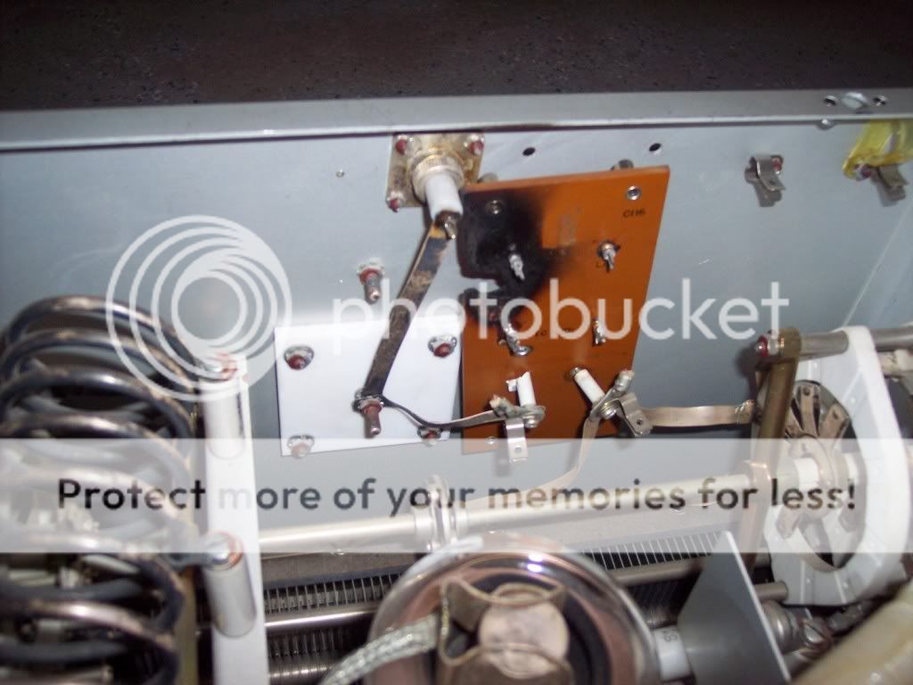
Kamikaze, in your opinion, what was on the circuit board mounted to the wall that fried? I am thinking that it had something to do with an output indicator, Maybe an RF Ammeter?

.
 
Looks like you are correct. The GPT-750 uses an R.F. ammeter with an external shunt.

The deck may have been operated without a load. I'd just bypass the tank output right to the connector making sure there's a good safety choke across it.

Looks like the clips on the top RH of your pic are to hold a shunt replacement shorting bar. Manuals for this beast are on the WWW.
 
How does a person "pad" for 160?

There are 8 switch locations aside from the plate capacitor tab on the tank switch. I can't figure out which bands they are for...was this deck used for warc bands or something?

Are you saying that I can leave all circuitry the same, but drive the cathodes, ground the grid, add bifilar chokes to the filaments, and run it? There was a coil on each input to the filaments, but not sure it's rating...see the under chassis view...Would they not work as chokes?

I can easily bypass the burned board and run RF out directly to the connector. I can't remember seeing a safety choke though. I'll re-look at it.

Thanks,

~D
 
I think the best advice you have been given so far is to leave the RF deck intact and buy some 3-500Z tubes for it. You'll need 100 watts to drive it but it's going to produce much more with those tubes and be a manageable project that won't require extensive knowledge if planed correctly. Buy the Triode Board sold online to complete this project. It will give you all the needed control, bias, and metering circuits for the project. It will simplify a quality build while adding over current protection for those new 3-500Z tubes.

Do not make any major modifications or changes in the layout of that RF deck. It's beautifully designed. Yes it looks strange that the vacuum plate cap is centrally mounted but that's done for a reason on many RF decks that cover this range of HF nicely. You need a short low inductance path from the anode to that cap and the tank coil for it to work at 10 meters. You also need to fit a lot of inductance in the tank coil to get down to 2 MHz.

The amp will probably tune the high end of 160 but may run out of loading capacitance lower in frequency. Then you would add a fixed value door knob cap in parallel with the load variable. That is padding. The tank coil may also be short to reach low into 160. It has 8 bands because it's continuous coverage from 2 to 30 MHz and not just ham bands. The two filament coils are no good for cathode drive down to low HF. You'll need use the bifilar type otherwise the filament supply will start loading down the drive on the low bands.

I think the board that mounts to your transformer had the high voltage rectifiers mounted on it. The transformer is also rated at 1.5 KW continuous and should be very capable of producing 2.5 KW DC input for ICS use. The burnt board on the back of the RF deck may have had a RF shunt. The part that confuses me is the RF output and HV input appear to be the same connection. How do you use a DC shunt choke to insure HV does not appear on this RF output? You'll need to look at the schematic for that info. Whatever snapped into the holder on that board was also on the chassis a few inches to the right as a spare. Common military practice.

To sum up, use 3-500Z's because getting it to work properly grid driven as a tetrode is going to be quite difficult. The screen grid input section is all missing because it was likely part of the output stage of the unit that drives this one. If your driver is tubes or you can use an antenna tuner between it and the amp, skip the tuned input unless you really want to add it. Either way, I would do that last after the amp has been tested and debugged. Otherwise if you run into problems you'll have to troubleshoot both the input and the amp together.
 
Yes, the best rf deck layouts always installed vacuum variables vertically with very short low inductance leads to the rest of the tank.

R.F. Parts sells cheap bi-filiar chokes. The existing coils probably won't work.

That plate iron originally used a choke input filter. Do you have the choke? It will be a two terminal piece of iron. Leaving that choke out would give you some serious B+ and really make a pair of 3-500s play but.... I'd be worried about the plate transformer without a choke. Older plate transformers used higher resistance windings and sometimes don't work well with cap input filters.

Original rectifiers were tube type.

Good advice to leave the layout as is and work with it.

Personally I'd skip a triode board with 3-500Z's as it is not really needed. Tubes with easily evaporated grids benefit from the excellent control with the boards. All you need is zener bias and grid current metering.

This deck was mounted on a very heavy duty pair of rack slides. The rf output connector slid into a stationary finger in the cabinet. The other one is parallel and is used with a jumper when the deck is run in the open position.
 

dxChat
Help Users
  • No one is chatting at the moment.