• You can now help support WorldwideDX when you shop on Amazon at no additional cost to you! Simply follow this Shop on Amazon link first and a portion of any purchase is sent to WorldwideDX to help with site costs.

Mismatched tube impedence-can I use in parallel?

Duhfactor

Member
Dec 22, 2010
7
0
11
55
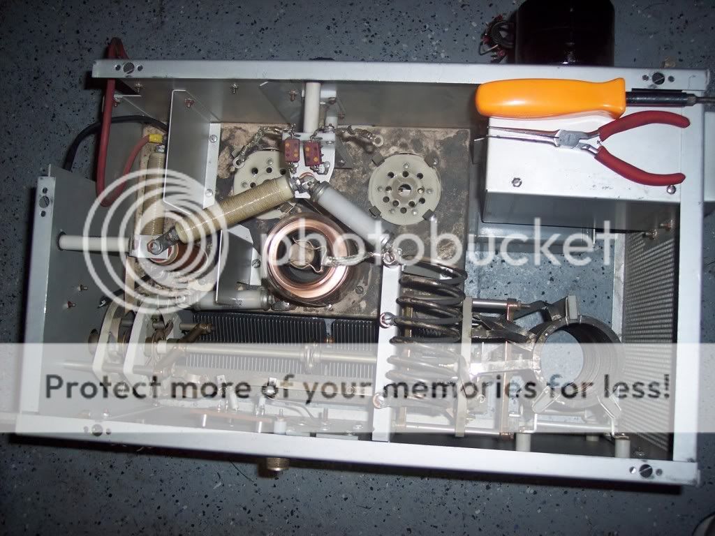
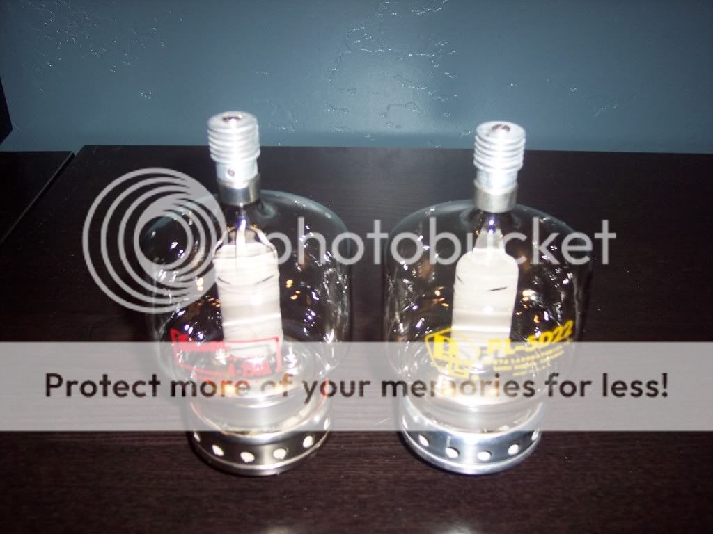
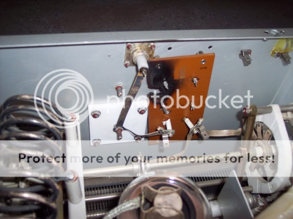
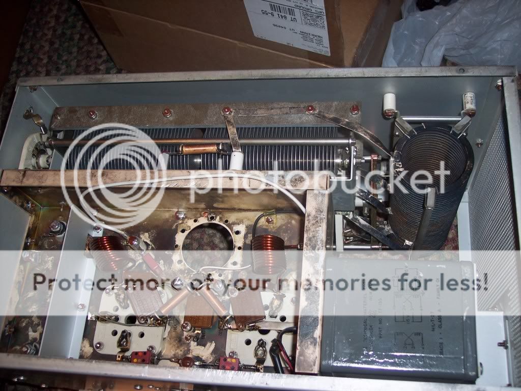
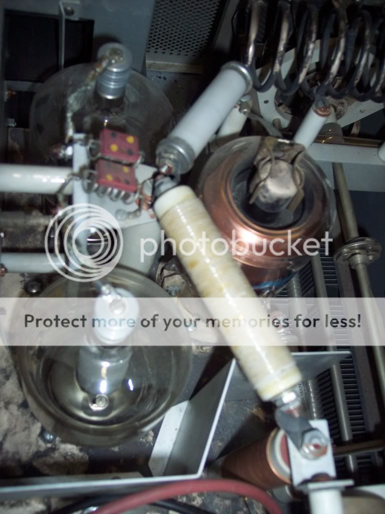
I have picked up a surplus amp ( I think military) that had twin 4-250A tubes run in parallel. I plan to rebuild this amp using these two tubes, and repair and modify it to run in AB1, grid driven. The problem I have is that one tube is an Eimac 4-250A, the other is a Penta Laboratories 4-250A (PL). Their spec sheets are somewhat different, with different grid and plate current ratings, as well as impedence ratings. I can't remember exactly, but I think the Eimac calls for 11,400 ohms, and the PL tube calls for 6,400 ohms. Can I still run these in parallel, or should I try to locate another tube that is made by the same manufacturer to closer match the specs? The amp did have one component fried close to the output antenna jack, probably the blocking capacitor or an inductor, (it was removed, so i'm not sure exactly what it was that fried the board). I can't find anything that is giving a direction for me. Any advice will be appreciated.

Thank you,

~D
 

Input and output impedances are pretty much consistent with the drive levels... IE, the input impedance of a GROUNDED GRID amplifier won't be the same at 50 watts in as it will with 150 watts in. That's the reason you can't use the MFJ technique on a cold tube.. It needs to be warm, and at drive levels expected.

OTOH, with a grid driven, R terminated grid drive amplifier, you usually CAN do the above.

What I'm trying to say here is, as long as the tubes have similar Cin Cout and the internal C is approximately the same, and the Mu of the tube is the same, you'd be OK. Which I doubt.

The cool thing is you can run 4-125s to 4-400s :) As long as they PHYSICALLY fit. You might not see anymore Pout, due to the rest of the amps design and limitations, but it does make for cheap tube replacement.....

Incidentally, I've run from 4-250s to 4-400s in my SB220, just ground the grids directly.

--Toll_Free

I'm going to check the tube specs tonight when I get home, but as I recall, there is some differences there. I'm not sure if the Mu is the same, but I'm thinking they are some different as well. On your SB220, have you ever run mismatched tubes, ie: different manufacturers?

~D
 
My experience with many Penta tubes (made in China) indicates when new they tend to have more gain then the original Eimacs. The bad part is the anodes are not designed as well and don't take the same abuse. Typically when used together with an older USA tube, the Penta will hog more of the bias current and drive. Easily identified by it's anode turning red well before the other. Of course all of this depends on how much use either tube has had.

Since they are in parallel, bias the thing up for the correct idling current running a single tube. Then change the tube and see if the other is in the ballpark. If you notice a significant different in the DC bias currents between the two tubes at the same bias voltage, it usually gets worse at high power when drive is applied. Getting unmatched tubes to play nice together in a single stage is hit and miss. Chances are better when you can see no physical differences in construction between tubes. I bet you can see differences in these two.

Could this also occur if I run a used Eimac, and purchase a new Eimac to go along with it?
 
Could this also occur if I run a used Eimac, and purchase a new Eimac to go along with it?

Yes it could but the chances would be reduced so long as your original Eimac tube has low hours and has not been abused. Keep in mind Eimac has not made any glass tubes in about a decade. If you find NOS they will be priced high.
 
Even with 2 NOS tubes, shouldn't the amp be nuetralized? Or am I in left field?

Any grid driven amplifier with that type of gain should be neutralized to keep it stable. Neutralization will also increase efficiency by allowing the plate current to dip at resonance. Some people swamp the grid with lots of resistive padding in an attempt to control self oscillation in the absence of neutralization. That kills the gain of the tetrode and doesn't help a bit with obtaining a nice dip in plate current at resonance.
 
Okay, I had pictured in my mind neutralizing an amp to insure that multiple tubes were working equally as hard. I was told that even swapping in 2 new tubes from the same lot, the amp shoud still be neutralized. But I see people grabbing what ever tube they have on hand and plucking it in with no ill effects.
 
LET’S PLAY STUMP THE TECH

I have picked up a surplus amp ( I think military) that had twin 4-250A tubes run in parallel.

Surely, this amplifier has a Model number, a manufacturer’s name or, maybe even post some pictures of it, that way, we could give you intelligent answers and not just guesses.

I plan to rebuild this amp using these two tubes, and repair and modify it to run in AB1, grid driven.

Yeah, well tell us about the hardware as it sits, how much B+ does the X-former produce, what frequencies does it operate on now and, where do you plan to use it?

The problem I have is that one tube is an Eimac 4-250A, the other is a Penta Laboratories 4-250A (PL).

Problem, what problem? Build the amplifier and worry about the tube brands at a more appropriate time.

Their spec sheets are somewhat different, with different grid and plate current ratings, as well as impedence ratings. I can't remember exactly, but I think the Eimac calls for 11,400 ohms, and the PL tube calls for 6,400 ohms.

The “Problem” that a lot of in-experienced “Teks” run into is, they get too hung up on some number in a design circumstance trying to achieve some goal that they cannot measure; build the amplifier! What are you going to use for a screen voltage supply? How about your negative going supply voltage? Have you ever built a Grid driven Tetrode before?

Can I still run these in parallel, or should I try to locate another tube that is made by the same manufacturer to closer match the specs?

Transistors have “Specifications”, Tubes have Guidelines; as long as you operate your tubes (same or different manufacturer) within the operating parameters of the tube, all will work.

The amp did have one component fried close to the output antenna jack, probably the blocking capacitor or an inductor, (it was removed, so i'm not sure exactly what it was that fried the board).

It might have been a safety choke if, it was near the output jack connected to the low impedance side of the Load tuner; bad news is, if that was fried then that means that there was a problem in the DC Blocking Cap back on the high impedance side of the Tune capacitor.

I can't find anything that is giving a direction for me.

I can only suggest that you look at the schematic for the Pride DX 300 or Pride DX 1000, I believe that that amp uses a Tetrode tube in a grid driven configuration.

Any advice will be appreciated.

Go to Yahoo Groups and look for RF amplifier groups.

Thank you,~D

If you build it, it will work.

.
 
O.K., thanks for the advice. Here are some answers to the questions as I know it now.

The individual I purchased it from never used it, and had very little information other than "look at those pretty tubes". I've wanted to build one from scratch, and learn as I go. It's missing parts, but came with a 2500V 600mA supply, that is sealed military unit. I plan to crack it open tomorrow to see if it has any caps, filters, etc inside, or if it is just a transformer. I'm not sure yet which frequencies it operated on, but plan to use it on HF bands 160-10. I will need to figure out the tank coil in more detail as I get there.

I didn't know (yes, noob here, first amp project) if differing tube specs would require differing values in components of the amp circuit during the build process, thus began asking the above question to help me get an idea.

I was considering using B+ dropped down for screen voltage, and wasn't sure how close the "guidelines" needed to be to operate the tubes without frying something else...Sounds like I'm worried about nothing here...

Thanks for the newsgroup link.

The attached file is one schematic I found that I was looking at closely. opinions?

~D
 

Attachments

  • 59hb2104250Aamplifier.pdf
    2.2 MB · Views: 480
The attached pics are of the tubes, amp w/tubes removed, jennings vacuum variable, burned board, and front panel of the power supply ( or transformer..) etc..

100_2862.jpg


100_2863.jpg


100_2861.jpg


100_2834.jpg


100_2866.jpg


100_2836.jpg


I purchased both amp and power supply for 250.00 total....didn't think it was too bad of a deal for a project. Attached is the only file I could find that matched the numbers on the power supply. The case of the amp is missing panels, etc., couldn't find any numbers on it...

~D

~D
 

Attachments

  • MIL-T-27E.PDF
    6.3 MB · Views: 197
Well, it seems that you have the PA section from a Military transmitter of some vintage; most of the hard parts are already there, just positioned in inconvenient places.

If possible, you would like to keep as much of the output network intact.

z100_2862.jpg


1. I would want to move the Plate tune to the front panel

2. I would move the Plate choke to where the Plate Vacuum Variable used to be placed.

3. Relocate the High Voltage input.

4. Items dotted in red are redundant, could be ommitted.

5. You have to add Input jack, Input tuning and, Antenna Switch Relay.

The Handbook circuit that you settled on will work, the only thing I would do to update it is to use Bias control protection boards; separate boards for each tube.

I don't know what they were trying to do on the bottom of the chassis so, I would completely gut all the wiring and install something I had confidence in.

.
 
Any idea what might have been on that board that got fried? I'm planning to gut the whole chassis, categorize all my parts, and re-do from scratch in a new enclosure. I pulled the apparent "power supply" lid off, also a surplus military unit, to find it to be a massive transformer only. I welded the lid back on, and now will need to plan a power supply.

100_2868.jpg


100_2869.jpg


100_2871.jpg


~D
 
What you have there is the R.F. deck from a Technical
Material Coproration GPT-750.

IMHO Put in the tubes with the most dissipation possible. That would be 4-400s if staying grid driven which really isn't the easiest thing to do in a linear amp. A pair of 3-500Zs would plug right in. Add a filament bifilar choke and drive the cathodes. Done.

The tank circuit is capable of a little over 3 kw P.E.P. from 2-30 MHZ. 160 might need some padding. Same rig could be supplied plate modulated which is why the tank circuit is so beefy.

O.K., thanks for the advice. Here are some answers to the questions as I know it now.

The individual I purchased it from never used it, and had very little information other than "look at those pretty tubes". I've wanted to build one from scratch, and learn as I go. It's missing parts, but came with a 2500V 600mA supply, that is sealed military unit. I plan to crack it open tomorrow to see if it has any caps, filters, etc inside, or if it is just a transformer. I'm not sure yet which frequencies it operated on, but plan to use it on HF bands 160-10. I will need to figure out the tank coil in more detail as I get there.

I didn't know (yes, noob here, first amp project) if differing tube specs would require differing values in components of the amp circuit during the build process, thus began asking the above question to help me get an idea.

I was considering using B+ dropped down for screen voltage, and wasn't sure how close the "guidelines" needed to be to operate the tubes without frying something else...Sounds like I'm worried about nothing here...

Thanks for the newsgroup link.

The attached file is one schematic I found that I was looking at closely. opinions?

~D
 

dxChat
Help Users
  • No one is chatting at the moment.