• You can now help support WorldwideDX when you shop on Amazon at no additional cost to you! Simply follow this Shop on Amazon link first and a portion of any purchase is sent to WorldwideDX to help with site costs.

Modifying FatBoy 4 pill 2879C Keying Relay Assistance

NightThumper

South of Pittsburg
Nov 8, 2017
655
1,551
153
The FatBoy amp has developed a sticking keying relay. It happens daily and frequently while in use. It doesn’t completely un-key and switch back receive. I have tried different radios and same issue. There is no power output/wattage while the relay is stuck. A quick key of the microphone and it un-sticks and goes back into receive.

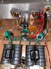
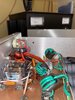
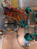
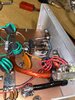
I’m looking for clarification on the purpose/function of several components in the attached picture.

1. What is the purpose of the orange (radial) capacitor going from ground to the relay?
2. What is the purpose of the mica capacitor going from ground to the relay?
3. What is the purpose of the disc capacitor going from one lead of the orange capacitor to one leg of the RF sensing transistor?
4. Then in all that mess there is a diode (I’m assuming a common variety) going from ground to the center leg of the RF sensing transistor?
5. On the opposite side there is a large orange disc capacitor going from ground to the relay.
6. What transistor is being utilized for RF sensing?

Modification questions:
1. Should I upgrade the keying relay to something more stout?
2. I want to also install an RCA jack/or re-purpose the remote jack so I can manually key the amp and bypass the RF sensing when desired. Does this involve adding a second relay SPST to bypass? What type/rating relay is needed?
3. Is their anything else I can do to improve this aspect of the circuit while I’m replacing the sticky relay?

Final question…what’s involved if I want to add a switch for bias/delay for SSB while I’m at it?

Thanks in advance
Brad
KE0XS
South of Pittsburgh
 

Attachments

  • 5010DF91-4E2A-46FC-87EC-22264E8849B3.jpeg
    5010DF91-4E2A-46FC-87EC-22264E8849B3.jpeg
    1.7 MB · Views: 38
  • 5A284ADD-4A01-4648-87C0-7096B5DB2B82.jpeg
    5A284ADD-4A01-4648-87C0-7096B5DB2B82.jpeg
    1.4 MB · Views: 36
  • DC8A6EA0-F643-4E43-AA0C-D4AC717C9D31.jpeg
    DC8A6EA0-F643-4E43-AA0C-D4AC717C9D31.jpeg
    2.2 MB · Views: 34
  • E7C9BAE6-DFB5-4BAA-9511-F1BFDCFBE8CC.jpeg
    E7C9BAE6-DFB5-4BAA-9511-F1BFDCFBE8CC.jpeg
    1.5 MB · Views: 34
Last edited:

Hey Brad,
Sounds like the amplifier might be going into oscillations and generating enough rf to keep itself keyed. The swr issues are part of the same problem, these things are tuned on the edge of their capability in order to look good on the meter. The feedback 100ohm resistors going from the transistors output to the input are barely enough to keep it from running away. My new practice is to double these up to make more negative feedback at 50 ohms. This is what I have done on my xforce and Carl built amps. My thread about my xforce smoked will show you what I did. I am sorry I haven't posted pictures of the Carl like I said that I would in your other thread. But it's just like what I did on the xforce. Be careful, when the amplifier stays keyed, it could potentially damage your radio.
Chris
 
  • Like
Reactions: AudioShockwav
Chris,
I had wondered about it going into self oscillation. This would be the first time I’ve had an amplifier do that. I have enough of those 2 watt 100 ohm resistors on hand. I forgot to mention that the resistor on the output combiner looked like it had gotten hot and was brownish/burned so I replaced it. So everywhere there’s a 100 ohm resistor you doubled it there by dropping it down to 50 ohm?

The first photo is of the browned/burn resistor. The other photo is of all five of the 100 ohm resistors.

Thank You
Brad
 

Attachments

  • 5C9910FD-E434-4E25-A6B4-BB41C11AAD20.jpeg
    5C9910FD-E434-4E25-A6B4-BB41C11AAD20.jpeg
    1.8 MB · Views: 43
  • E57A714C-2625-4430-924B-D87159137B0B.jpeg
    E57A714C-2625-4430-924B-D87159137B0B.jpeg
    2.1 MB · Views: 42
Chris,
Self oscillation would explain why on two separate occasions I saw an absurd power spike of 1200 watts on my output meter. Yes I immediately got of the key.
 
Last edited:
  • Like
Reactions: AudioShockwav
Chris,
Self isolation would explain why on two separate occasions I saw an absurd hours spike of 1200 W on my output meter. Yes I immediately got of the key.
The burnt 100 ohm on the output combiner means that one pair is working harder than the other pair for some reason. Hopefully the transistors are matched, but if not then that would be the cause. If they are matched, then I would suspect tolerance stacking on the components around the transistors to be the cause. Something is different on one pair. The only way I know to track that down is to remove each component and check the values, capacitors and resistors.

The oscillation problem, double up the resistors that are alongside the transistors. They have a disc capacitor on one end. One for each transistor.

Also might be a good idea to pull one leg of the output tune cap to verify that it's value hasn't changed. This can also contribute to the oscillation problem.

Chris
 
Good information. Since I replaced the burnt resistor I’ve used the amp quite a bit and it appears whatever caused it hasn’t returned. That resistor got burnt when I didn’t notice the first time when the relay wasn’t un-keying and returning to receive because immediately afterwards I could smell it. That’s when I noticed it hadn’t un-keyed. Since then I keep an eagle eye on what it’s doing.
 
Chris,
Thank you very much for pointing me in the right direction. As of my extensive testing this morning the relay has not stuck since modifying the negative feedback per your expert advice. In addition no smoke was let out…LOL. I did noticed that output wattage decrease by almost 50 watts. Instead of seeing roughly 700 PEP with the normal drive of 45 watts PEP and 14.1 volts, PEP is now about 650…no biggie. I did order some 5% caps which I may install at a later date on the negative feedback circuit…those 104 0.1uF caps. Thanks again my friend.

Brad
KE0XS
South of Pittsburgh
 

Attachments

  • 6EFEF995-2017-433D-89C5-D027973D50A8.jpeg
    6EFEF995-2017-433D-89C5-D027973D50A8.jpeg
    1.7 MB · Views: 30
On another note if someone would like to school me on the purpose/function of those various components on the keying relay in my initial post I would be very grateful. If you don’t want to post here PM me and I’ll send you my phone number.

Thanks
Brad
 
Chris,
Thank you very much for pointing me in the right direction. As of my extensive testing this morning the relay has not stuck since modifying the negative feedback per your expert advice. In addition no smoke was let out…LOL. I did noticed that output wattage decrease by almost 50 watts. Instead of seeing roughly 700 PEP with the normal drive of 45 watts PEP and 14.1 volts, PEP is now about 650…no biggie. I did order some 5% caps which I may install at a later date on the negative feedback circuit…those 104 0.1uF caps. Thanks again my friend.

Brad
KE0XS
South of Pittsburgh

Glad it worked out, the information I shared was given to me by other members here while working on my own amplifier. I give them the credit and thank WWDX for giving us a great place to learn and grow. (y)
Chris
 

dxChat
Help Users
  • No one is chatting at the moment.