
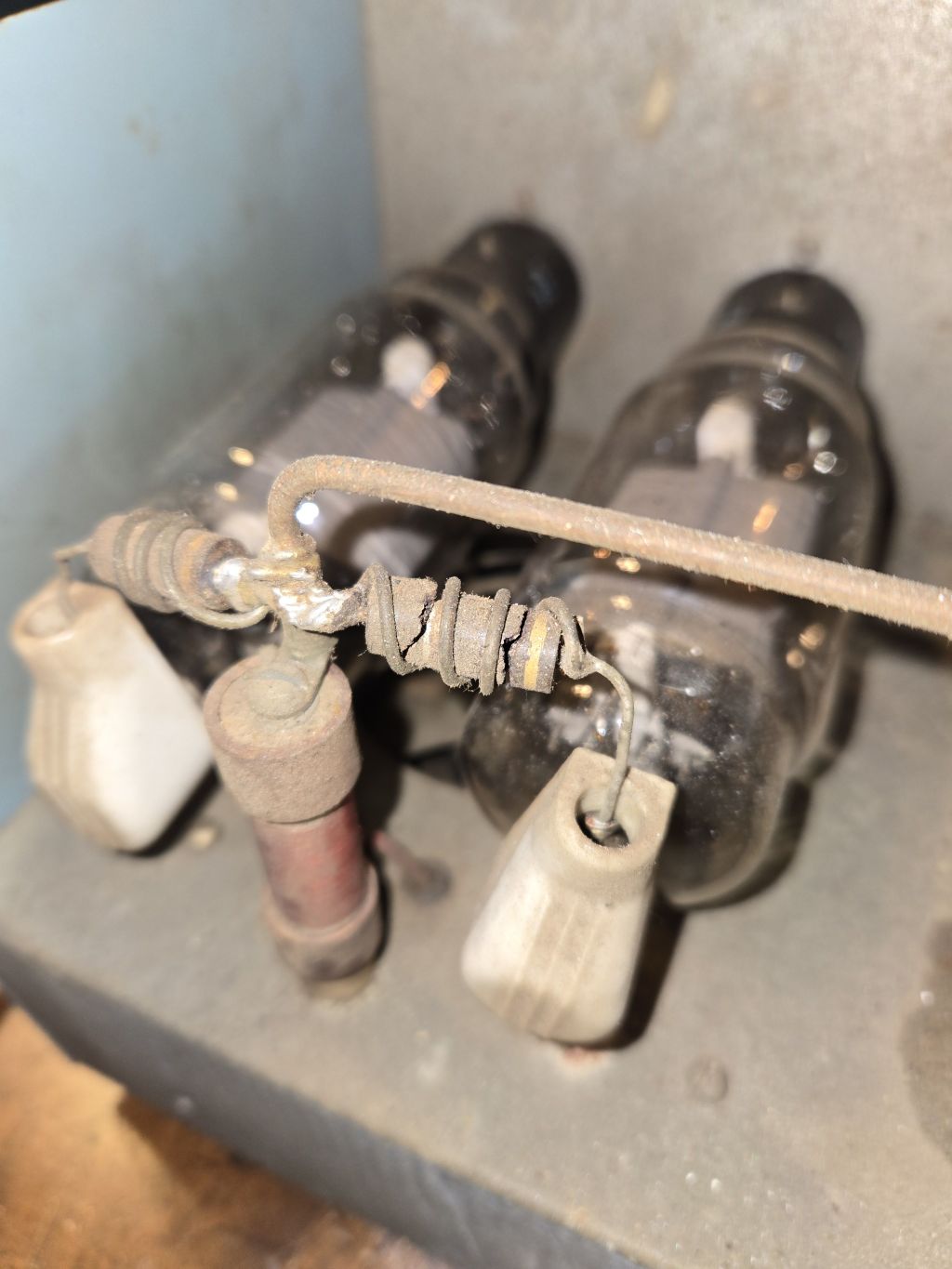
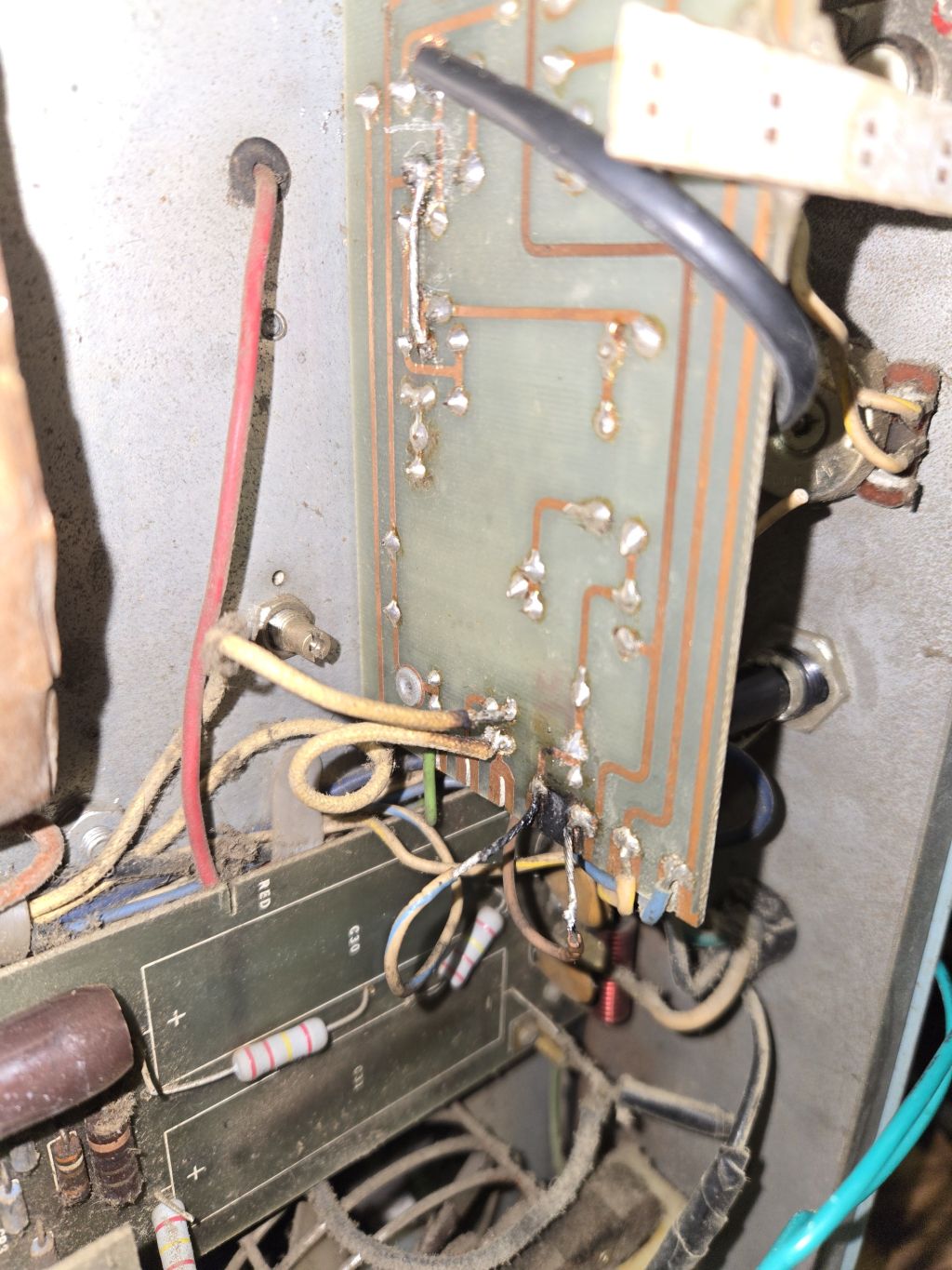
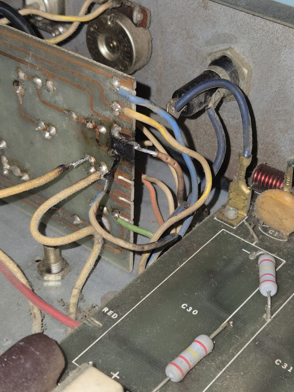
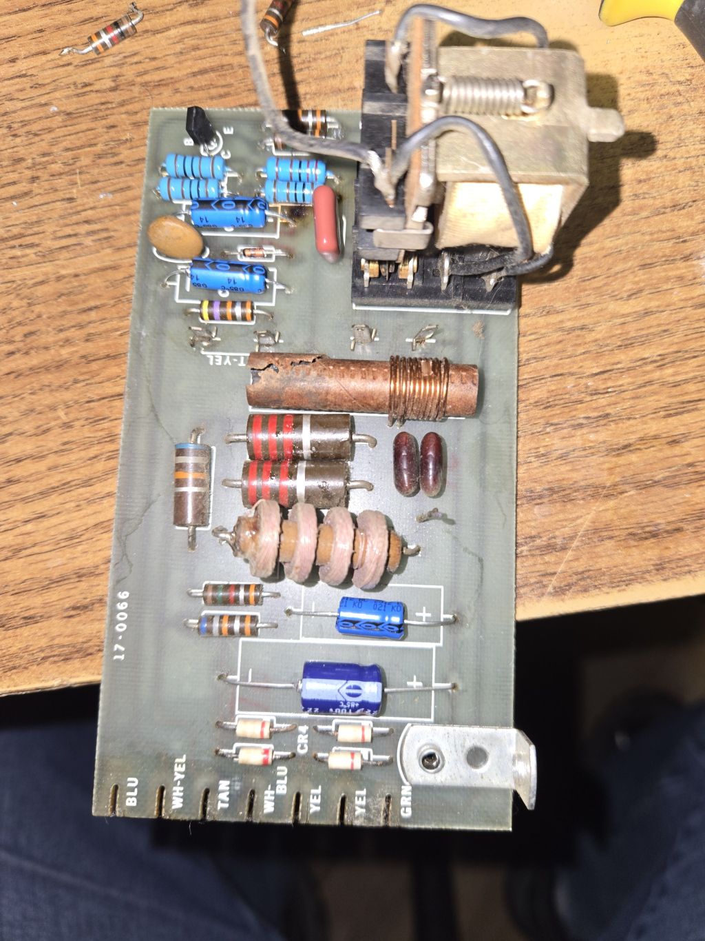
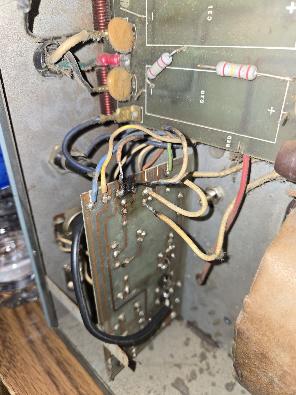
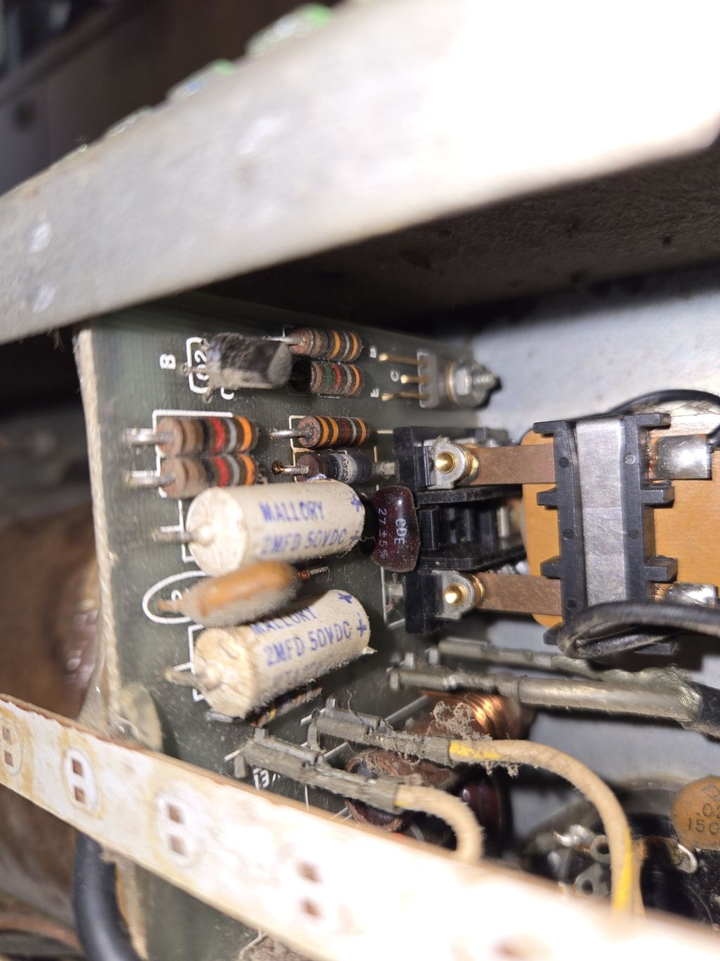
Hope Im posting this in the right area, but I have a couple questions that you all may be able to help me out with. To start, about 6 months or so ago I got a Mohawk 10 5b, it was in pretty rough shape, driver tube had been removed and the wires and coil for the driver tube had been hacked out. The capacitors for the driver high voltage had also been removed. The small voltage regulating tubes have also been removed. Relay keying circuit was not working as most of the components on the board were burned up, and a makeshift footpedal switch was being used on it. The input from the relay was going directly into the 572b tubes so the input SWR was off the charts. The parasitic chokes on the 572b's were in rough shape as the resistors to them were cracked and burned up. Since then, I replaced all the components for the relay keying circuit and that is now working properly, and so is the SSB delay. I cleaned up all the connections and rebuilt the parasitic chokes with carbon film resistors. What I have done, is look at the wiring diagram for a heathkit SB-200 and decided to make this amp a high drive amp. I built a L network matching circuit for the input essentially by using the values from the SB-200 diagram as a starting point. First attempt, I used a adjustable inductor with an inductance of 0.137uH to 0.22uH and was only able to achieve SWR input of about 5:1. I rebuilt with a larger inductor with a value of 0.289uH to 0.384uH and I was able to achieve a SWR input of about 2.8:1. I did run the amp with this SWR input and it was working pretty well. When modulating, the SWR drops to roughly 2.1:1 at full modulation from my radio, with is about 30 watts. The amp will swing about 500w PEP with this 30 watt input. My question regarding this, is can I add another adjustable inductor in series to get a better input match, or is it just better to get a higher value inductor to get a better match?
My other question, is regarding the high voltage. Acording to the owners manual of the Mohawk, it says the final plate voltage should be between 2500v-3000v. The meter on the amp shows the voltage at 2000v. Is that the manual correct as the voltage should be showing between 2500v-3000v? The capacitors on the 572b voltage boad appeard to have been replace at some point in time, but I would estimate it has been at least a decade. I am planning on re-capping that board after I get the input SWR resolved. Thank you in advance for any advice.
The images show what it looked like when I got it, and some of the work I did.
My other question, is regarding the high voltage. Acording to the owners manual of the Mohawk, it says the final plate voltage should be between 2500v-3000v. The meter on the amp shows the voltage at 2000v. Is that the manual correct as the voltage should be showing between 2500v-3000v? The capacitors on the 572b voltage boad appeard to have been replace at some point in time, but I would estimate it has been at least a decade. I am planning on re-capping that board after I get the input SWR resolved. Thank you in advance for any advice.
The images show what it looked like when I got it, and some of the work I did.
Last edited:

