• You can now help support WorldwideDX when you shop on Amazon at no additional cost to you! Simply follow this Shop on Amazon link first and a portion of any purchase is sent to WorldwideDX to help with site costs.
  • A Winner has been chosen for the 2026 July 4th Retevis RA89R Giveaway! Click Here to see who won!

Mohawk 10 5b modification help

Nomadd1776

New Member
Sep 24, 2025
11
1
3
46
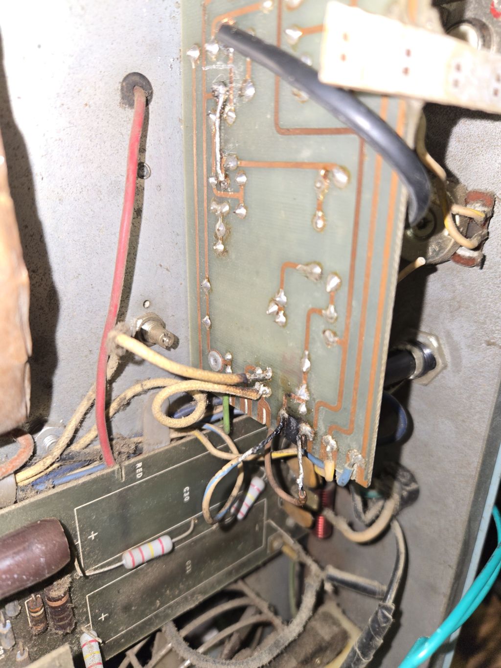
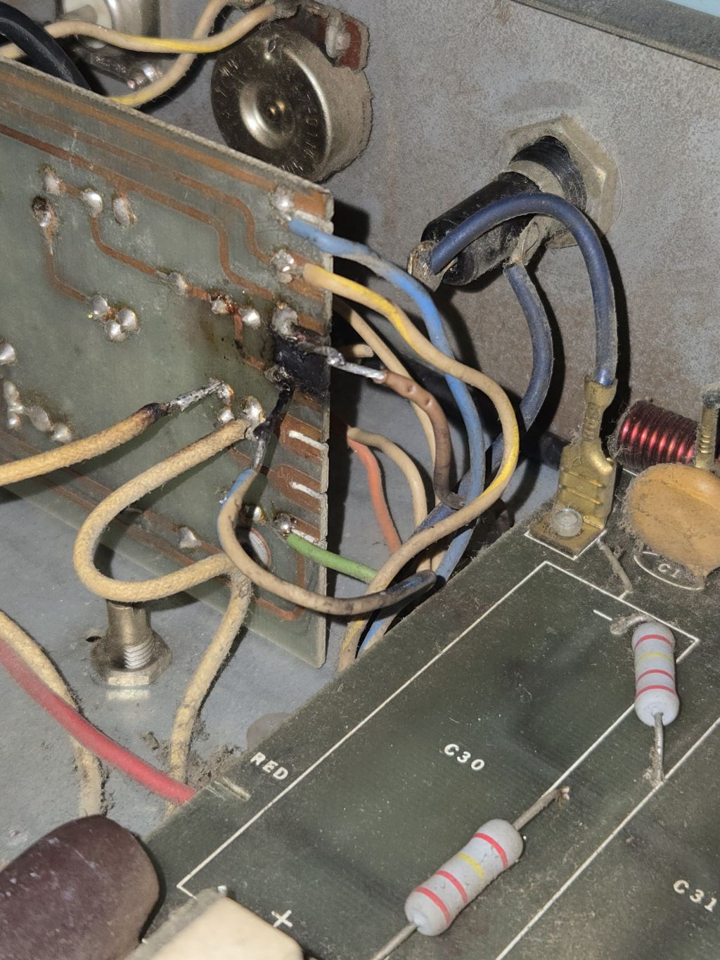
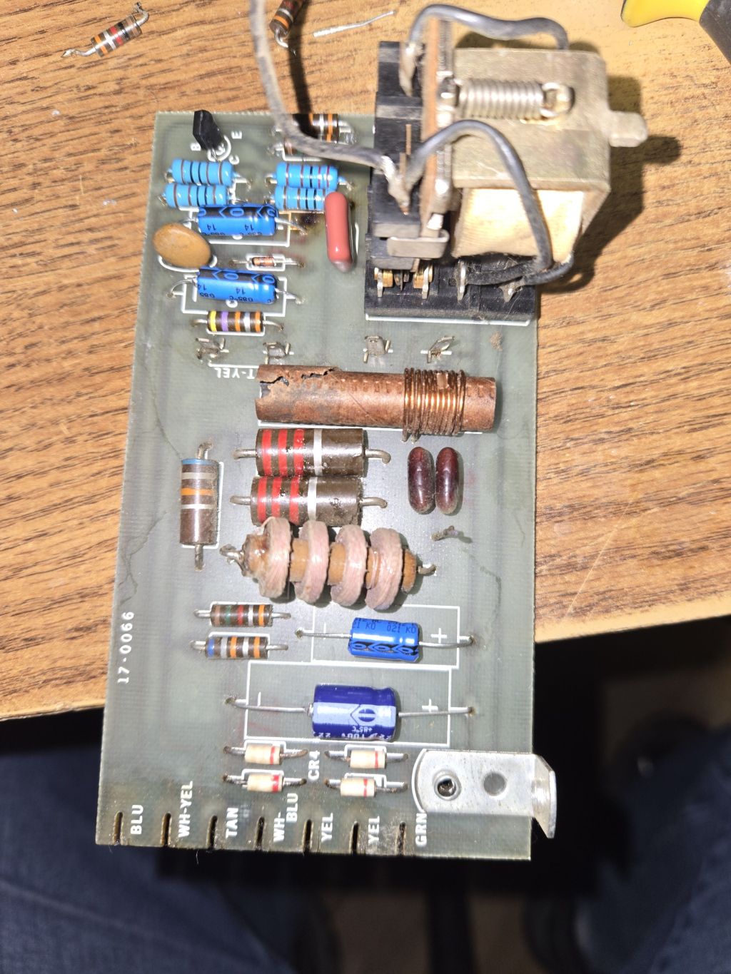
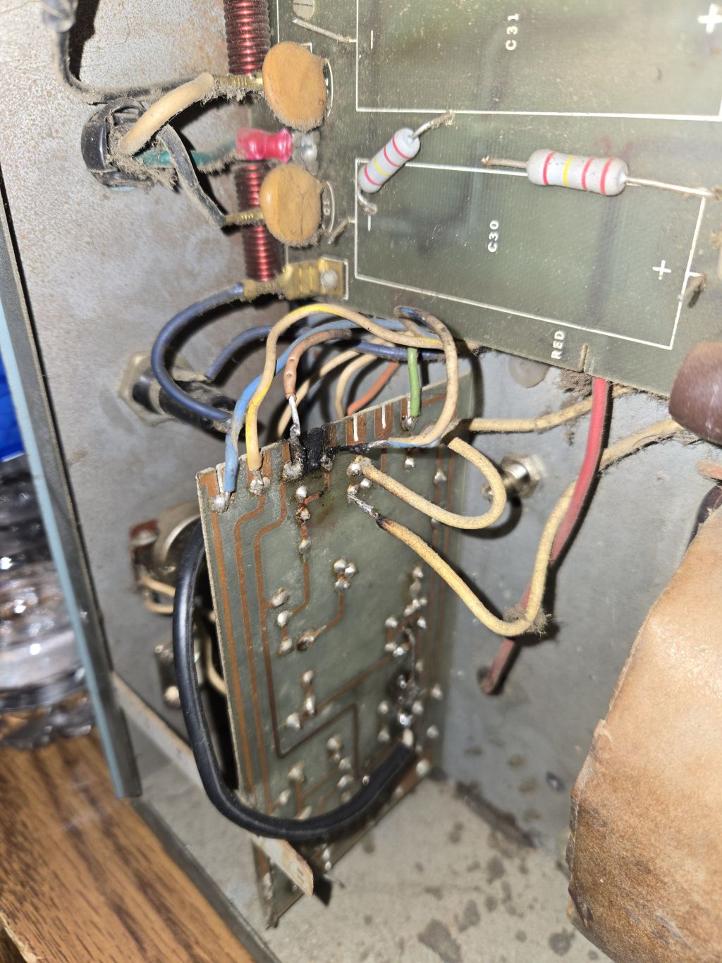
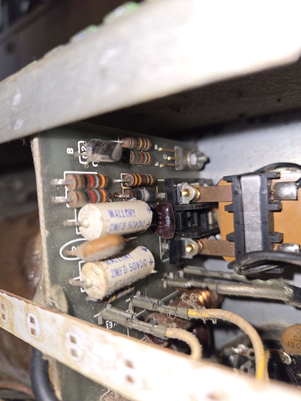
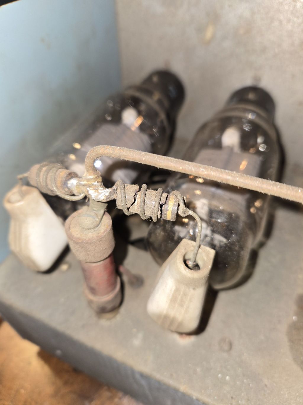
Hope Im posting this in the right area, but I have a couple questions that you all may be able to help me out with. To start, about 6 months or so ago I got a Mohawk 10 5b, it was in pretty rough shape, driver tube had been removed and the wires and coil for the driver tube had been hacked out. The capacitors for the driver high voltage had also been removed. The small voltage regulating tubes have also been removed. Relay keying circuit was not working as most of the components on the board were burned up, and a makeshift footpedal switch was being used on it. The input from the relay was going directly into the 572b tubes so the input SWR was off the charts. The parasitic chokes on the 572b's were in rough shape as the resistors to them were cracked and burned up. Since then, I replaced all the components for the relay keying circuit and that is now working properly, and so is the SSB delay. I cleaned up all the connections and rebuilt the parasitic chokes with carbon film resistors. What I have done, is look at the wiring diagram for a heathkit SB-200 and decided to make this amp a high drive amp. I built a L network matching circuit for the input essentially by using the values from the SB-200 diagram as a starting point. First attempt, I used a adjustable inductor with an inductance of 0.137uH to 0.22uH and was only able to achieve SWR input of about 5:1. I rebuilt with a larger inductor with a value of 0.289uH to 0.384uH and I was able to achieve a SWR input of about 2.8:1. I did run the amp with this SWR input and it was working pretty well. When modulating, the SWR drops to roughly 2.1:1 at full modulation from my radio, with is about 30 watts. The amp will swing about 500w PEP with this 30 watt input. My question regarding this, is can I add another adjustable inductor in series to get a better input match, or is it just better to get a higher value inductor to get a better match?

My other question, is regarding the high voltage. Acording to the owners manual of the Mohawk, it says the final plate voltage should be between 2500v-3000v. The meter on the amp shows the voltage at 2000v. Is that the manual correct as the voltage should be showing between 2500v-3000v? The capacitors on the 572b voltage boad appeard to have been replace at some point in time, but I would estimate it has been at least a decade. I am planning on re-capping that board after I get the input SWR resolved. Thank you in advance for any advice.

The images show what it looked like when I got it, and some of the work I did.
1024-13656.jpg
1024-13655.jpg
1024-13654.jpg
1024-13653.jpg
1024-1365.jpg
1024-13652.jpg
 
Last edited:

More inductance is just more inductance in this circuit. Shouldn't matter whether its one or two coils that add up to the needed inductance. Seems to me we use between 7/10 and 1 uH for that. An open-core coil you can squeeze or stretch to trim the optimum value works for us. Try 7 or 8 turns solid wire wound on a half-inch form. If you have to spread the turns too far to get the input SWR low, remove a turn, squeeze them back together, lather rinse repeat.

Bear in mind that the designer of this box failed to read the manufacturer's advice about mounting this tube on its side. The filament is in the shape of a "W". It tends to sag a bit as it warms up. Mounting the tube with pins 1 and 4 in the vertical plane will make that "W" vertical. If it sags, it does so into the empty space between the grid wires. But turned with the W flat, it can sag and touch the grid.

Bad juju, that.

My recommendation to a customer with one of these is to turn it on its side so the 572Bs are vertical inside. This fixes the orientation problem. The cost of this fix is quite attractive compared to drilling out the rivets holding the tube sockets and turning each tube socket 90 degrees. Some component leads won't reach the proper tube-socket lug and have to be extended. So far every customer chooses the cheap option.

73
 
Last edited:
Thank you for the reply and tips, Ill will definitely look into either changing the tube orientation or just standing the amp on its side.

Do you know if the operating voltage I have is correct? Meter reads about 2000v on standby, and when modulation on SSB, the peak voltage drop is around 1600v-1700v. I am planning on re-capping the high voltage board but just want to know if there is anything else I should be looking at also.
 
Here is a grubby diagram of the Mohawk 10. The HV transformer winding is marked 1000 Volts. Should produce about 2800 Volts from the full-wave voltage doubler circuit. This is at the very optimistic side for the 572B tube. If the filter caps in the high voltage are original, they will cause grief soon. Not if but when. How reliable the front-panel volt meter will be is questionable. Checking the resistors in that part of the meter circuit may reveal bogus resistance values. They drift with age.

Weak filter capacitors will also cause a large voltage drop when the tubes draw current. Every electrolytic in it needs to go. You can probably just remove the two filter caps for the driver tube's B+ supply.

Removing the built-in driver is the only sane approach. It's just way too easy to overdrive.

73
 
Here is a grubby diagram of the Mohawk 10. The HV transformer winding is marked 1000 Volts. Should produce about 2800 Volts from the full-wave voltage doubler circuit. This is at the very optimistic side for the 572B tube. If the filter caps in the high voltage are original, they will cause grief soon. Not if but when. How reliable the front-panel volt meter will be is questionable. Checking the resistors in that part of the meter circuit may reveal bogus resistance values. They drift with age.

Weak filter capacitors will also cause a large voltage drop when the tubes draw current. Every electrolytic in it needs to go. You can probably just remove the two filter caps for the driver tube's B+ supply.

Removing the built-in driver is the only sane approach. It's just way too easy to overdrive.

73
The filter caps for the driver tube were already removed from the driver voltage supply board when I got it. the 4 caps that are visible on the 572b voltage board (I have not removed the board to inspect the other side yet) appear to have been replaced at some point in time, but I am planning on replacing all 8 of them anyways. Thank you for the tip on checking the resistors in the meter circuit, I will definitely check them or just replace them. Thank you, I appreciate your help and advice.
 

dxChat
Help Users
  • No one is chatting at the moment.