• You can now help support WorldwideDX when you shop on Amazon at no additional cost to you! Simply follow this Shop on Amazon link first and a portion of any purchase is sent to WorldwideDX to help with site costs.

Need Help Galaxy DX-2547 Factory MOSFET No RF Out

SuperLid

Sr. Member
Feb 6, 2020
558
509
103
NY/NJ
Anyone out there have a semi voltage chart for this radio? I have only found one for the bipolar version. Also, this radio has the RCI mixer, which seems to differ from the Siemens. I could use a datasheet on this as well.

This all started when I got this radio and started to un-screwdriver it, as well as a few other things that needed to be repaired. All was going well, until I tried to expand the range of the clarifier. That resulted in a fire in the clarifier, smoking the clarifier control. I did make some circuit changes and cleaned up the mods. I have since returned the radio back to stock now and I have no RF output. It isn't the usual suspects.

I have low level signal (a few mW) on the service monitor. I have AM mod, but am not sure, but believe I don't hear SSB mod. I have RX.

I have checked: There is bias, the FET's test good, the pre-driver is good, the shorting bar is in place and good, Q54 is testing good. The TX/RX LED does switch. I have 8-9V on TX and RX.

I guess my head is spinning from this one and I am missing service data, like the voltages in the PA and the datasheet on the mixer. I don't have a mixer to shotgun with, or I probably would have done it already. I have been over the soldering and possible burned traces.

Thanks,

SuperLid
 

There is no "Sams Photofact" on any of the Galaxy radios. The last one was CB293, which was printed in the 80's, decades ago. A Galaxy DX2547 is a 2000's or newer radio. cbtricks.com has these
EPT069610C main board
This is for the Bipolar final version, the main differences are that they switched out the TX Driver from a 2SC2166 and Final from a 2SC1969, for IRF520 MOSFETs (both), and changed the bias circuits to match. The speaker amplifier was also changed from a TA7222 to a TDA2003.

EPT069611Z main board
You can use the Service Manual for the Bipolar radio for most (but not all) voltages, excepting the above mentioned changes.
 
Last edited:
There is no "Sams Photofact" on any of the Galaxy radios. The last one was CB293, which was printed in the 80's, decades ago. A Galaxy DX2547 is a 2000's or newer radio. cbtricks.com has these
EPT069610C main board
This is for the Bipolar final version, the main differences are that they switched out the TX Driver from a 2SC2166 and Final from a 2SC1969, for IRF520 MOSFETs (both), and changed the bias circuits to match. The speaker amplifier was also changed from a TA7222 to a TDA2003.

EPT069611Z main board
You can use the Service Manual for the Bipolar radio for most (but not all) voltages, excepting the above mentioned changes.
I need the voltage chart for the MOSFET version. What is out there, I already have and not helpful.The AF amp, mixer and balanced modulator were all changed, in addition to the PA transistors.
 
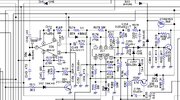
DX2547 bipolar Balanced Mod.jpg
DX2547 Balanced Modulator AN612

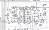
DX2547 MOSFET Balanced Mod.jpg
DX2547 Balanced Modulator MOSFET version RCI-612 - looks like a direct pin-for-pin drop in replacement for the AN612 (copied? rebranded? Made their own version?)

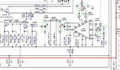
DX2547 bipolar TX Mixer.jpg
DX2547 bipolar TX Mixer - SO42P

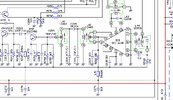
DX2547 MOSFET TX Mixer.jpg
DX2547 MOSFET TX Mixer - RCI-6130 - looks like a direct pin-for-pin drop in replacement for the SO42P.

Same part R and C numbers, same values. So the voltages should be the same or nearly the same.
 
  • Like
Reactions: Shadetree Mechanic
View attachment 61093
DX2547 Balanced Modulator AN612

View attachment 61094
DX2547 Balanced Modulator MOSFET version RCI-612 - looks like a direct pin-for-pin drop in replacement for the AN612 (copied? rebranded? Made their own version?)

View attachment 61095
DX2547 bipolar TX Mixer - SO42P

View attachment 61096
DX2547 MOSFET TX Mixer - RCI-6130 - looks like a direct pin-for-pin drop in replacement for the SO42P.

Same part R and C numbers, same values. So the voltages should be the same or nearly the same.
I thought the same. However, when I reviewed the datasheet for the SO42P, Vss is on pin 4, which is tied to ground on the RCI6130.
 
Vss is Voltage Source, or Ground (Vdd (Pin 5) is Voltage Drain, or +V, because Electrons flow from Source to Drain). Looking at the schematics of both SO42P and RCI-6130, Pins 1, 4, 6, 9 and 14 are all grounded.
 
  • Like
Reactions: Shadetree Mechanic
Vss is Voltage Source, or Ground (Vdd (Pin 5) is Voltage Drain, or +V, because Electrons flow from Source to Drain). Looking at the schematics of both SO42P and RCI-6130, Pins 1, 4, 6, 9 and 14 are all

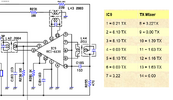
View attachment 61120
???
By Voltage Chart​
What I don't have, is a voltage chart that pertains to the MOSFET PA section. I have not had time to work on that radio this week. But I will possibly at some point today. Adding to the confusion, I found a rather old datasheet for the Siemens SO42P while searching around. It showed Vss on pin 4. This must have been in error.
 
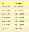
The voltage chart is full of errors, it can't be trusted, I am chasing ghosts. Look at the voltage chart for IC9. Pins 10 and 12 are tied, yet they show different voltages. I still have no TX power out, but the pre-driver, driver and final get fairly warm when in TX a while. Unfortunately, I do not have another radio like this for comparison. What I did find, is that the radio is very low quality. The PCB copper is the thinnest I have ever encountered in a CB radio. I have worked on a few Galaxy's, but I don't remember them being this bad.
 
When you see Siemens - then you get predictable Results.

When you see RCI in the Chips' ID - stamp - run the other way...

Thats why I posted the "???".

Wildly varying quality from RCI - you can almost guess the year it was made by just the quirks it had during operation.

Pretty much what you had to do is look at the schematic,

Thinking...
  • ok, I see 5 gets power, so 2 and 3 will be close in DC values
  • - Pin 11 and 12 - Do I care? Or Should I care? They Feed each other and match impedance output to input thru that broadbanded Resistor
  • - so you'll see AC there all the time (If L44 and L43 are sending signal to be mixed...)
  • 9 and 6 SHIELD 7 and 8 - 11 and 13 with 14 (6, 9 and 14 Signal GND to cans) have signal float DC level at 1/3rd to 1/4th of input DC voltage
    • - e.g. - have sine wave but bias is present and is pulled down even greater (to lower DC Bias voltages) when the loading of the coupling coil to those pins is correctly "ringing"
  • - hence both doorbells - front and back (PLL and VCO/Clarifier) are loading the chip with full bias current so DC is pulled down when fully working
  • - the higher the DC float voltages on Signal pins - the less signal it is using.
 
Last edited:
  • Like
Reactions: Shadetree Mechanic
Have you checked the circuit board for solder blobs that might be shorting traces together? Sometimes the quickest way to find them is by scrubbing the entire board with a dry toothbrush.

Is there a chance that it could just be blown final or driver, whatever MOSFETs are in it? I know that IRF520 and IRF520N are different.

Just asking...........
I already covered that in my original post...
 
Last edited:

dxChat
Help Users
  • No one is chatting at the moment.