• You can now help support WorldwideDX when you shop on Amazon at no additional cost to you! Simply follow this Shop on Amazon link first and a portion of any purchase is sent to WorldwideDX to help with site costs.

Need help with side mic cobra 29 Ltd classic

This also raises another question...

I'm asking this because of what I see in your photo...

I just noticed this....
Missing Part.gif

I took a picture of a more modern Cobra 29 - and I noticed you have a DISC Cap that is FOLDED over the spot the part would be...

You may be missing the key part - the Varactor itself.

In todays radios - they are SMT devices, and soldered under the board using the PADS the original DISCRETE part would be.

See if you even have one!

Else we may have found out why it won't work.
 
  • Like
Reactions: Shadetree Mechanic
thanks for chiming in Andy.

im sure you'll agree that he needs to start right at the beginning of the alignment procedure to adjust L22 for max before he can do much of anything else.

i was assuming that the PLL was locking because he said that his RX/TX light was turning from green to red.

now when he says that L19 makes no difference, i want to see what happens when L22 is peaked.
LC
 
To answer your questions Andy, I unfolded that cap, and yes there does appear to be a varactor present, and every single electrolytic capacitor in the radio has been changed by me. Where there was 6.3 and 10volt caps, I put in either 16volt or 25v. I did not mess with any of the values, for instance if it had a 4.7uf I put a 4.7uf back in. Lowboy to answer your question there was really not very much glue in this radio at all.

Also: I made some progress this morning, I tried messing with l22 and never could get it to make a difference. I pulled the ferrite core all the way out a few times and tried bottoming it out etc.

So to make a long story short, I ended up swapping in the l22 can from the parts radio.
So then I turn the radio on with my dvom positive lead hooked to r88, negative to board ground... I proceeded to start turning l22 up and down. A few turns cw from where l22 had been set in the parts radio. I see the numbers start to change on the dvom. It changes from 4.90v to 3.54. So I turn the radio to channel 19 key the mike and now I’m able to adjust l19 to 3.2v.... but still no tx.
I think this is a good sign though.

Andy here is a picture of where I bent that cap back up straight
And all the old electrolytics
 

Attachments

  • A07313E8-679F-44AB-93B7-3EACF84FA081.jpeg
    A07313E8-679F-44AB-93B7-3EACF84FA081.jpeg
    1.6 MB · Views: 13
  • BFC8750D-EBCF-4061-9A20-E7F8F03E269D.jpeg
    BFC8750D-EBCF-4061-9A20-E7F8F03E269D.jpeg
    1.6 MB · Views: 13
  • Like
Reactions: Woody-202
L23 "trims" the 10.240 oscillator - but to scope it? That may not provide much help.

You'll need to know whats being combined - it's AFTER the signals are mixed together from the L22 and L23 do we see anything close to 27MHz and that's at the Predriver and that L19 mess...Then you'd have to determine your channel frequency compared to actual frequency you should be on, on that channel.

So, keep going - you're making progress.

L23 will need more power - (Scotty reference intended) from L22 to tune the band. So you'll have to do the channel 1 then channel 40 flip flop back and forth until you find a good centering of L22 BETWEEN the two extremes of the channel plan. YOU DO ADJUST L23 to help with this - this is part of the PLL loop output to BOTH TX 10.240, (Combines with L19 and TX out of L20) and the Radios 10.240 IF at L6/L7 2nd IF downmix.

To help with RX, you can tweak L18 -the ~17MHz downmix for both 1st IF/Mixer amp L5/L4 works with...(This is what tunes your channel IF for SELECTION of your channel.

L23 Peaks out the 2nd IF mixer to grab the 455kHz that feeds into L7 - that goes into L8 and L9 then your Detector. L23 also provide the 2nd half or the 10.240 "push" to mix that comes off of the L19 / L18 mess - and then that output is cycled thru that TWIN core L21 - a band pass filter that is part of IC1 - that you'll need to send to L20 and then onto the Predriver mess...

Do you or have you - a working schematic that's close enough to that radio to guide you?

Because the better the RX performance - as that section improves, you will be able to center the TX alignment with just basic understanding of peaking coils and spread of bandpass.

L24 - is your TRUE TIMING REFERENCE of the 10.240 that L23 uses and L19 - SYNCs with.

You're doing great!
 
Thanks for your help Andy, the schematic I have been looking at is euro radios redraw from cb tricks, it’s the easiest one for me to try and interpret.

I haven’t really had a chance to mess with it any since yesterday morning. Other than I got the rf probe built now
 
I’m still grasping at how all this stuff works, and how all the parts work together. I did make a small discovery. On pin 1 ic3 I have 17.755mhz on pin4 10.240mhz and on pin 8 27.255. I’m still struggling on tracing the signal. I feel like it’s close to working though... if only I actually knew what I was doing lol.
 
That signals are appearing on the various pins is a great sign.

Replacing the Electrolytics was possibly the best tune up change so far.

You located the Varactor...

You replaced L17...

Learning to do a tuneup is not difficult, but then it does help to know where to start.

You didn't know that when you got here...I'd say you're making progress....

I'd say your patient is well on the way to recovery...
 
ill post more later, but i just wanted to mention real quick since this is a Cobra 29LTD thread that there is a mistake on the CBtricks 29LTD page, and one of the links that says it's for the 29LTD has the alignment for the 25LTD inside it.

this can cause great confusion if you are new to tuning up radios.
so, i always post the link to the accurate ones. the correct version to use is the one with two links.
if you are using the other one, well, don't.

http://www.cbtricks.com/radios/cobr..._st/graphics/29ltd-st_29wx-st_sm_pg1_pg11.pdf

http://www.cbtricks.com/radios/cobr...st/graphics/29ltd-st_29wx-st_sm_pg12_pg34.pdf

LC
Thanks loose cannon,

I’m able to to trace rf/ 27mhz from pin 7 of ic3 to r62. I loose it right there. I’m about to pull my hair out from messing with this thing.
When I hook my rf probe to r61 I get nothing I am not able to peak l20. I have pulled both r62 and d14 they are both good. And r62 tested as a 2.2k just like the schematic shows. I just can’t figure out why I’m losing it here. I feel like this thing is close to working.
 
Here is a picture
 

Attachments

  • 0DE2B88B-01CD-4440-BAD8-970B2C284311.jpeg
    0DE2B88B-01CD-4440-BAD8-970B2C284311.jpeg
    92.2 KB · Views: 8
  • 316B7B33-5AA8-42EF-9121-882BAAA4FDFD.jpeg
    316B7B33-5AA8-42EF-9121-882BAAA4FDFD.jpeg
    338.5 KB · Views: 6
I'm adding this in, because I realize we need to do this in steps to help you...

First...
DVM - Volts setting...

Rx mode - measure voltage at BANDED end of D17...
(adjust Delta-Tune - does voltage on BANDED side of D17 vary?)

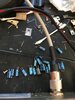
Tx mode - Measure voltage at it's BANDED end - D18
(These are by L20/L24 see photo below)

TR16 - test probe that - during RX and During TX report voltages...


Now - read below because if PLL Power Good pin isn't working like it should - you won't be able to send any voltage to turn on TR16 - thru R62.

The Mixer NEEDS two signals for it to produce an output - else it's pin 7 stays low, and D14 won't send any power back to the PLL's Power Good sense line - and the signal "disappears"

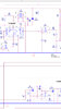
R63 and C65 is RF out from MIXER (Takes in 17MHz from L19 TXCO - and 10.240 from PLL Xtal.)..

Did you test that Pre-Driver transistor 2SC941 - TR16?

If that parts' bad, you lose your signal - check voltage there - in TX then in RX - Junction R61 and R62.- C65 and R63 are a series circuit from L20's output. That is the actual 27MHz.

R62 provide DC bias into the Pre-Driver Base - it's the "Power Good" signal from the PLL's Pin 15. It is supposed to turn on TR16. Should give you something like 1.2V to a low as 0.7V - enough to turn on the Base of TR16 nothing more - RF from R63/C65 takes care of the rest.

When you TX, Pin 3 of the MIC Jack shorts to Ground - Goes low - so that means Pin 9 of the PLL also goes low.

That then forces the PLL to look at Pin 15 - it looks for Pin 7 output of the TX Mixer - thru D14.
(It also forces the PLL to SHIFT it's output of L19 coil UPWARDS 455kHz)

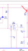
So let's back up a moment - you have a tuning control called Delta-Tune - see if any mods or work was done to it. Why? Because if it had work done to it, and They/it blew up the potentiometer - you would not get any TX or any working RX either. Check D17 and D18 - they switch from TX straight thru to RX thru the Delta-Tune.

Look for any work in that section.

See/Check - if they did a jumper or other work - this line runs the 10.240 - so if RX works but TX doesn't this may be where the problem is. R99 is a 4.7K "fixed value" to set TX frequency and then the Delta-Tune swings voltage up and down from that mid-point R99 and D18 set - but only on RX.

When you TX...
RX line gets pulled low because Pin 3 of the Mic Jack shorts to ground.

Test the Junction of D17, D18 (Banded side-goes towards L25) in both RX and TX modes, if one (RX) has-shows a voltage then it's gone when in the other mode(TX) , there's a problem with sending 10.240 to the PLL in TX.
Inanymode.jpg

If there is no power in the junction of D18 ad D17 to L25 at any time - you wouldn't be able to send any RF thru L20 into TR16 to even start the chain. A bad mod, or blown part in D17/D18 or any part of the Delta-Tune area going to L25 to power the Xtal - would kill TX because you lose your oscillator because D17/D18 isn't sending any power or getting thru any power because of a bad mod to the Delta-Tune circuit. No 10.240MHz signal to go to the MIXER IC3 (TX mixer)
 
Last edited:
  • Like
Reactions: Shadetree Mechanic
I have to post this or I will forget. Im getting 7.72volts on the middle pin of tr16 in tx. In rx just mv jumping around. I couldn’t find any mods in the d17,d18 area. In rx I get 4 something volts on I believe the banded ends of d18/d17, then in tx I get 4 something volts on both sides of the diodes

I had swapped out tr16 out of the parts radio a few days ago but never tried to take any voltage measurements.
.
 

dxChat
Help Users
  • No one is chatting at the moment.
  • @ Wildcat27:
    Hello I have a old school 2950 receives great on all modes and transmits great on AM but no transmit on SSB. Does anyone have any idea?
  • @ ButtFuzz:
    Good evening from Sunny Salem! What’s shaking?