
You are using an out of date browser. It may not display this or other websites correctly.
You should upgrade or use an alternative browser.
You should upgrade or use an alternative browser.
-
You can now help support WorldwideDX when you shop on Amazon at no additional cost to you! Simply follow this Shop on Amazon link first and a portion of any purchase is sent to WorldwideDX to help with site costs.
-
A Winner has been chosen for the 2026 July 4th Retevis RA89R Giveaway! Click Here to see who won!
New thread to debate V-4000
- Thread starter nosepc
- Start date
To make a "gain" there must be a loss.
Directional antennas lose signal in a direction to increase it in another.
The vertical not, then emitted equally in all directions, however much radiation smash lobe therefore should not speak of "gain" of a portrait but efficiency is not the same as performance.
Discuss whether an antenna is a fraction of dBi more than another, it makes no sense.More important is the direction of irradiation lobe, its simplicity, robustness, and size.
We know that the SIGMA IV SIRIO VECTOR 4000 has a higher radiation lobe of a 5/8 and a lot more than a GM or a dipole.
This is at 38 ° above the horizon, which benefits not for local use, and also doubt it's better than others in CB. for DX where one lobe of low degrees is required.
Maybe it's a good design for 80,40.30. and 20 meters. Where these degrees of irradiation are ideal, but not in CB.
nosepc.
You've also noticed the more time you spend in EZNEC making the model more similar to the antenna, the closer it gets to the unity gain 1/2 wave EZNEC mistakenly views it as. Previously, others could argue that was because the Sigma was just a fancy looking 1/2 wave J-pole. That all flies right out the window when you CAN'T use a 180 degree phase shift in the field to drive a second collinear element because it cancels the constructive cone radiation.
Well Donald, I'm more interested in finding out if Eznec is reliable or just junk.
You've seen the two S4 models I stacked together tip to tip and their variations described below.
1. The two S4's end to end models using a shorted phasing stub with two 106" wires 2" apart...I get exactly what I would expect. There is a nice collinear gain at a good low angle and the match for the setup remains almost exactly like the S4 by itself.
2. I did the same model with the radial cone area removed leaving a no cone 3/4 wave radiator, and the model went to heck in a hand basket.
3. I made model no cone model #2 by changing the radiator from 3/4 w to 1/2 w, and I got a model similar to model #1. IMO, this suggest that the model is simply two 1/2 wave models phased together. IMO this also suggest the S4 is nothing more than a effective 1/2 wave radiator that is raised up higher than others in its class...above the feed point.
I've said this before, if I could see some proof that Eznec does the S4 model in error, or that CST does it right...I could easily be convinced. I just need more proof than simple claims, an animated pattern from CST, or claims from your testing where for obvious reasons...you cannot post such results.
Donald, this is not personal, and I would never call you are Bob liars. I hope this is all about seeing if wa6byu can duplicate your findings.
If that happens...then I'll have to shut up, right?
I have more of foundation for my opinions that I just can't ignore. This does not make me right or wrong however.
From the first days of my realizing there was a CB antenna that was longer than a 1/2 wave...I was constantly told by my antenna mentor...the only difference was moving of the tip height up 5' feet higher over a 1/2 wave radiator.
I've said this before Donald, I believe the S4's current maximum is simply raised up higher above the feed point than a 5/8 wave radiator. This results in a nice gain over the others shorter wavelength radiators. IMO this is all there is too this great S4 design.
I also believe the up raised radial cone does manifest a collinear aspect that Cebik described to Bob, but the result is far less that you suggest and I attribute that to cancellation of out of phase currents in the cone area. It is like pushing the feed point 8'-9' feet higher than a typical vertical 1/2 wave.
Hopefully, we'll soon know for sure.
To make a "gain" there must be a loss.
Directional antennas lose signal in a direction to increase it in another.
The vertical not, then emitted equally in all directions, however much radiation smash lobe therefore should not speak of "gain" of a portrait but efficiency is not the same as performance.
Gain in verticals also comes from removing energy in the nulls of a pattern that contains these multiple lobes you complain of. When more than one element in a collinear radiates in phase, it also produces additional nulls in the pattern. That transfers more energy into the main lobe on the horizon. You know, the one you ignore.
Discuss whether an antenna is a fraction of dBi more than another, it makes no sense.More important is the direction of irradiation lobe, its simplicity, robustness, and size.
We know that the SIGMA IV SIRIO VECTOR 4000 has a higher radiation lobe of a 5/8 and a lot more than a GM or a dipole.
This is at 38 ° above the horizon, which benefits not for local use, and also doubt it's better than others in CB. for DX where one lobe of low degrees is required.
We know nothing of the sort, that is simply your misguided opinion. You'd be hard pressed to convince anyone that has a clue that the Vector has an inferior pattern compared to a 5/8 wave groundplane. Objectionable and avoidable high angle lobes are created whenever the antenna radiates an inverted phase along it's length. The bottom 1/8 wave of the 5/8 wave is well know to exhibit this characteristic.
Maybe it's a good design for 80,40.30. and 20 meters. Where these degrees of irradiation are ideal, but not in CB.
nosepc.
You've never even used this antenna, You only listen to people who have no clue when they provide you with your opinion about how it does not work. You have no access to accurate computer models other than the one I provided and you ignore. Not only is it a good antenna at HF for local and DX work, it's an effective option all the way through VHF.
Last edited:
Well Donald, I'm more interested in finding out if Eznec is reliable or just junk.
You've seen the two S4 models I stacked together tip to tip and their variations described below.
1. The two S4's end to end models using a shorted phasing stub with two 106" wires 2" apart...I get exactly what I would expect. There is a nice collinear gain at a good low angle and the match for the setup remains almost exactly like the S4 by itself.
2. I did the same model with the radial cone area removed leaving a no cone 3/4 wave radiator, and the model went to heck in a hand basket.
3. I made model no cone model #2 by changing the radiator from 3/4 w to 1/2 w, and I got a model similar to model #1. IMO, this suggest that the model is simply two 1/2 wave models phased together. IMO this also suggest the S4 is nothing more than a effective 1/2 wave radiator that is raised up higher than others in its class...above the feed point.
I've said this before, if I could see some proof that Eznec does the S4 model in error, or that CST does it right...I could easily be convinced. I just need more proof than simple claims, an animated pattern from CST, or claims from your testing where for obvious reasons...you cannot post such results.
Do you realize the entire idea of this test was to add a known 1/2 wave 180 degree radiator with currents and phase that are well understood and not in dispute, and use that to determine the constructive wavelength of the stock antenna by the phase shift required between collinear sections?
Your going off on your own ideas insured no one could gain any useful information in that area. You actually stacked two of the same radiators that are in debate over each other so there could not be an established reference point to work from. Then you ignored the test I described in EZNEC once it was explained in a way you could follow.
Donald, this is not personal, and I would never call you are Bob liars. I hope this is all about seeing if wa6byu can duplicate your findings.
When you call the CST model "my animation" or refer to my years of field experience and Bob's exchanges with Cebik as "our stories" Spare me your justification, I see it as I call it.
If that happens...then I'll have to shut up, right?
I doubt that.
I have more of foundation for my opinions that I just can't ignore. This does not make me right or wrong however.
From the first days of my realizing there was a CB antenna that was longer than a 1/2 wave...I was constantly told by my antenna mentor...the only difference was moving of the tip height up 5' feet higher over a 1/2 wave radiator.
I've said this before Donald, I believe the Ex.'s current maximum is simply raised up higher above the feed point than a 5/8 wave radiator. This results in a nice gain over the others shorter wavelength radiators. IMO this is all there is too this great S4 design.
I assure you your mentor was far behind the level of knowledge Cebik possessed. Your idea that the 8 extra feet of height is key, falls on the deafest ears you'll ever find. Know why? The difference in length on the band I work with is less than 2.5 feet. Almost none of the towers are under 100 feet and some are over 1000. How many more obstacles do you think this 2.5 feet is clearing to make a signal difference in these applications?
I also believe the up raised radial cone does manifest a collinear aspect that Cebik described to Bob, but the result is far less that you suggest and I attribute that to cancellation of out of phase currents in the cone area. It is like pushing the feed point 8'-9' feet higher than a typical vertical 1/2 wave.
Hopefully, we'll soon know for sure.
As though any future information is going to change the 90 degree phase shift required to drive another 1/2 wave section in the field. You figure out how that proves it has strong in phase currents over a 270 degree wavelength with phase correction. The person you're waiting on to repeat my tests already understands this direct connection.
Last edited:
Test
For some reason I couldn't get this page to load. I had to post in order to make it do it.
For some reason I couldn't get this page to load. I had to post in order to make it do it.
Gain in verticals also comes from removing energy in the nulls of a pattern that contains these multiple lobes you complain of. When more than one element in a collinear radiates in phase, it also produces additional nulls in the pattern. That transfers more energy into the main lobe on the horizon. You know, the one you ignore.
You only refers to time radiates "in phase", but never speaks when he does against phase as I have shown. ......................"Law of Reciprocity"
We know nothing of the sort, that is simply your misguided opinion. You'd be hard pressed to convince anyone that has a clue that the Vector has an inferior pattern compared to a 5/8 wave groundplane. Objectionable and avoidable high angle lobes are created whenever the antenna radiates an inverted phase along it's length. The bottom 1/8 wave of the 5/8 wave is well know to exhibit this characteristic.
So you say that the antenna is good "because it radiates down", but it does so minimal, most of her energy is lost in a high one above 30 °. That's wasting power
You've never even used this antenna, You only listen to people who have no clue when they provide you with your opinion about how it does not work. You no access to accurate computer model other than the one I provided and you ignore. Not only is it a good antenna at HF for local and DX work, it's an effective option all the way through VHF.
Never saw a Sigma IV antenna VHF or copy, this was already discussed in the same case, "someone" had not ASTROPLANE said, what is not true, I publish the photos.


evidence, and evidence are needed, not words.
NoSee, you publish cartoons while I've published the most sophisticated and accurate model anyone has ever seen on the design. I have also proved CST is right in multiple field tests. I'm not wasting the time to respond to your BS now. You've offered nothing to the forum while learning nothing from the forum and it was all your choice. Congratulations on wasting your opportunity to learn and remaining as ignorant as those who you allowed to give you your mistaken opinion.
Last edited:
You only refers to time radiates "in phase", but never speaks when he does against phase as I have shown. ......................"Law of Reciprocity"
You have not shown anything on the Vector that radiates out of phase. You have shown that you don't understand what the animation, and the stills from said animation, are showing you. Nothing more.
So you say that the antenna is good "because it radiates down", but it does so minimal, most of her energy is lost in a high one above 30 °. That's wasting power
You have also not shown that this antenna radiates at your claimed angle. If the radials were in fact horizontal then yes the antenna would have a high angle of radiation. The problem is the radials are not horizontal, and aren't even close. The burden of proof on this antennas radiation pattern is on your hands. Why do you not try and prove your words? The answer to that is simple, you cannot.
Never saw a Sigma IV antenna VHF or copy, this was already discussed in the same case, "someone" had not ASTROPLANE said, what is not true, I publish the photos.
...
evidence, and evidence are needed, not words.
Ah yes, your photos, at least two of which you posted recently were grossly misleading at best...
You have still yet to answer my challenge to you. I suppose it is to challenging for you. I suppose that is no surprise when all you have to back up your arguments are untrue words and pictures taken out of context...
The DB

Frankly, this thread is finished as far as nosepc is concerned.
I have learned a lot about how this antenna operates.
In fact, the info has been explained so well that even my dog now understands how the V4K works.
Thanks, Shockwave.
Nosepc offers nothing to this thread or this forum except for sport, and I will have none of that.
I have learned a lot about how this antenna operates.
In fact, the info has been explained so well that even my dog now understands how the V4K works.
Thanks, Shockwave.
Nosepc offers nothing to this thread or this forum except for sport, and I will have none of that.
Last edited:
Obviously, when they run out of arguments and reasons for, dodge the discussion on the subject, try to divert, or sermonize.

This is the Sirio GainMaster Antenna . She has no opposite phase currents.
The Vector 4000 SIGMA V4 also have powerfuls opposites currents.
If you follow the green color seen is the complete phase inversion and zero irradiation of the antenna, you will see that this antenna radiates it completely. This field does not exist in the GM
The CST model of a SIRIO VECTOR 4000 antenna diplay this in slow motion in the following animation.. Not see the who will not see

There are more individual images ..


time during which the antenna irradiation is auto canceled

Of course I see what you not see, but you confuse half-wave irradiation with the cone. Both are also not in phase as you say.
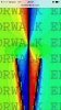
See that cone leaves a green color that is the variation of field AND PHASE CHANGE.
Therefore, the cone is in antiphase(yellow & blues colors) with the rest of the antenna.
In any case the emission of the cone also gives loss to the antenna.
In this picture, we see that the phases are perfectly changed inside and at the bottom of the cone, a part is blue, the other yellow, or that are not in phase
if they were on stage. the red color would be the left side and blue on the right, however are extrapolated, with an inverted phase of 180 degrees, so if there is emission is 180 degrees out of phase, which makes NEGATIVE
if so be collinear, and in phase, CST modeling both colors would be on the same side.
This is the Sirio GainMaster Antenna . She has no opposite phase currents.
The Vector 4000 SIGMA V4 also have powerfuls opposites currents.
If you follow the green color seen is the complete phase inversion and zero irradiation of the antenna, you will see that this antenna radiates it completely. This field does not exist in the GM
The CST model of a SIRIO VECTOR 4000 antenna diplay this in slow motion in the following animation.. Not see the who will not see

There are more individual images ..


time during which the antenna irradiation is auto canceled

Of course I see what you not see, but you confuse half-wave irradiation with the cone. Both are also not in phase as you say.
See that cone leaves a green color that is the variation of field AND PHASE CHANGE.
Therefore, the cone is in antiphase(yellow & blues colors) with the rest of the antenna.
In any case the emission of the cone also gives loss to the antenna.
In this picture, we see that the phases are perfectly changed inside and at the bottom of the cone, a part is blue, the other yellow, or that are not in phase
if they were on stage. the red color would be the left side and blue on the right, however are extrapolated, with an inverted phase of 180 degrees, so if there is emission is 180 degrees out of phase, which makes NEGATIVE
if so be collinear, and in phase, CST modeling both colors would be on the same side.
Obviously, when they run out of arguments and reasons for, dodge the discussion on the subject, try to divert, or sermonize.
This is the Sirio GainMaster Antenna . She has no opposite phase currents.
The Vector 4000 SIGMA V4 also have powerfuls opposites currents.
If you follow the green color seen is the complete phase inversion and zero irradiation of the antenna, you will see that this antenna radiates it completely. This field does not exist in the GM
The CST model of a SIRIO VECTOR 4000 antenna diplay this in slow motion in the following animation.. Not see the who will not see
There are more individual images ..
time during which the antenna irradiation is auto canceled
Of course I see what you not see, but you confuse half-wave irradiation with the cone. Both are also not in phase as you say.
See that cone leaves a green color that is the variation of field AND PHASE CHANGE.
Therefore, the cone is in antiphase(yellow & blues colors) with the rest of the antenna.
In any case the emission of the cone also gives loss to the antenna.
In this picture, we see that the phases are perfectly changed inside and at the bottom of the cone, a part is blue, the other yellow, or that are not in phase
if they were on stage. the red color would be the left side and blue on the right, however are extrapolated, with an inverted phase of 180 degrees, so if there is emission is 180 degrees out of phase, which makes NEGATIVE
if so be collinear, and in phase, CST modeling both colors would be on the same side.
Just to prevent this guys asinine persistence from tricking anyone who's learning, I'll explain this detail. The ONLY two images in the entire CST model that can provide you with useful phase and magnitude information is when the source current peaks at 90 or 270 degrees as shown here. The images he doctors up are closer to 0 and 180 degrees where currents will be lowest and highly misleading. He has to pick images where there is low current to support his misguided effort at fooling the forum.
Attachments
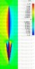
CST frame 21 above also demonstrates how the program displays radiation cancellation quite differently than what we see emitting from the cone. Since the currents are strongest in this frame, notice the field around the top of the cone emitting from the main vertical where the phase inverts. These two opposing fields are strong enough to overlap at their ends here. The cancellation is evident by the absence of radiation displayed by the green color in that area. Nothing like we see around the cone.
I also see no evidence of significant cancellation inside the cone. What I see is confinement of a strong out of phase current. The exact effect the engineer who built the CST model described. Does anyone see an opposing current on the inside of the cone with respect to the vertical that would assist those who think it's mostly a cancellation effect? The opposing current travels on the outside surface of the cone. Does anyone see much green shading inside the cone indicating the field was cancelled?
I also see no evidence of significant cancellation inside the cone. What I see is confinement of a strong out of phase current. The exact effect the engineer who built the CST model described. Does anyone see an opposing current on the inside of the cone with respect to the vertical that would assist those who think it's mostly a cancellation effect? The opposing current travels on the outside surface of the cone. Does anyone see much green shading inside the cone indicating the field was cancelled?
Last edited:
dxChat
- No one is chatting at the moment.