There is no phase loop or coil, or any device that makes the collinear antenna. Marketers call them as j-pole coaxial. So if radiate in phase, you would in another frequency by the length of the whole antenna, so that is not what you see, is the irradiation but out of phase.

You are using an out of date browser. It may not display this or other websites correctly.
You should upgrade or use an alternative browser.
You should upgrade or use an alternative browser.
-
You can now help support WorldwideDX when you shop on Amazon at no additional cost to you! Simply follow this Shop on Amazon link first and a portion of any purchase is sent to WorldwideDX to help with site costs.
-
A Winner has been chosen for the 2026 July 4th Retevis RA89R Giveaway! Click Here to see who won!
New thread to debate V-4000
- Thread starter nosepc
- Start date
There is no phase loop or coil, or any device that makes the collinear antenna. Marketers call them as j-pole coaxial. So if radiate in phase, you would in another frequency by the length of the whole antenna, so that is not what you see, is the irradiation but out of phase.
Since you seem so blindly fixated on denying the obvious, I'll be happy to assist in making that goal impossible to achieve. I will ask you to simply look at the picture and answer the questions yes, or no.
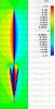
In the picture, do you see any colors emitting outwards from the cone that match any colors relating to phase and magnitude in the chart at the top right? The obvious answer is yes and that's because radiation is clearly present.
In the picture, do you see red and yellow emitting from both the top section and OUTSIDE of the cone on the left side and both showing shades of blue on the right? The obvious answer is yes because the radiation on the outside surface of the cone is in phase with the top 1/2 wave.
No coil or phase shift is required in this "non apparent collinear" since the phase of the main vertical radiator that is allowed to radiate has already been delayed by 90 degrees because it's lower 1/4 wave is confined within the cone and replaced with in phase currents along the outside surface of the cone.
Attachments
Several times I heard Freecell describe the radial cone on the S4 as a large expanding version of the coax, a continuation if you will right up to the bottom tip of the 1/2 wave radiator on top. He went on to claim that the angle of the elements relative to the radiator produced a very smooth transition of the coaxial currents, just like the coax, right up to the bottom end of the 1/2 wave radiator above...and I believe him until I started trying to understanding more about feed lines in my casual look at "Reflections II."
Does this sound reasonable from one of the old guard supporting the S4 design and its merits above all other CB verticals in its class? Can you explain?
Does anyone believe, as a result, we see common mode currents at play in S4 design and the CST animation? Can you also explain with a few words?
Can you explain how the current develops in the cone and where it emanates from and goes to...besides the obvious?
Can you indicate where we see high current points on the radiator inside of the cone, the upward slanting elements of the cone, and the top 1/2 of the radiator.
Using the animation still below, can you generally indicate, with words or an image of you own, any idea of the current magnitude and phase sign using the color graph provided? If you understand the graph then please indicate the phase value in a/m as noted, and the sign of the value where you think it goes on the image.
For example: the red tip might be - 0.0476 a/m or the middle of the top 1/2 wave might 2.37 a/m, etc., for the areas around the cone too.

I'm just curious what other's think.
Does this sound reasonable from one of the old guard supporting the S4 design and its merits above all other CB verticals in its class? Can you explain?
Does anyone believe, as a result, we see common mode currents at play in S4 design and the CST animation? Can you also explain with a few words?
Can you explain how the current develops in the cone and where it emanates from and goes to...besides the obvious?
Can you indicate where we see high current points on the radiator inside of the cone, the upward slanting elements of the cone, and the top 1/2 of the radiator.
Using the animation still below, can you generally indicate, with words or an image of you own, any idea of the current magnitude and phase sign using the color graph provided? If you understand the graph then please indicate the phase value in a/m as noted, and the sign of the value where you think it goes on the image.
For example: the red tip might be - 0.0476 a/m or the middle of the top 1/2 wave might 2.37 a/m, etc., for the areas around the cone too.
I'm just curious what other's think.
Several times I heard Freecell describe the radial cone on the S4 as a large expanding version of the coax, a continuation if you will right up to the bottom tip of the 1/2 wave radiator on top. He went on to claim that the angle of the elements relative to the radiator produced a very smooth transition of the coaxial currents, just like the coax, right up to the bottom end of the 1/2 wave radiator above...and I believe him until I started trying to understanding more about feed lines in my casual look at "Reflections II."
Does this sound reasonable from one of the old guard supporting the S4 design and its merits above all other CB verticals in its class? Can you explain?
Does anyone believe, as a result, we see common mode currents at play in S4 design and the CST animation? Can you also explain with a few words?
Can you explain how the current develops in the cone and where it emanates from and goes to...besides the obvious?
Can you indicate where we see high current points on the radiator inside of the cone, the upward slanting elements of the cone, and the top 1/2 of the radiator.
Using the animation still below, can you generally indicate, with words or an image of you own, any idea of the current magnitude and phase sign using the color graph provided? If you understand the graph then please indicate the phase value in a/m as noted, and the sign of the value where you think it goes on the image.
For example: the red tip might be - 0.0476 a/m or the middle of the top 1/2 wave might 2.37 a/m, etc., for the areas around the cone too.
I'm just curious what other's think.
I think the most logical source of the currents on the outside of the cone would be CMC. Since the cone is tuned for perfect 1/4 wave resonance, it is the path from the feedpoint where the CMC is radiated.
I really don't see any point in trying to extrapolate in words what the exact magnitude of radiation would be at any given point. That is the beauty of the image from this model. It provides a visual representation of magnitude and phase as the radiation currents propagate away from the antenna and it does so in way under 1000 words.
The intriguing fact here is that the CST model revealed Cebik's analysis of a "non apparent collinear" to be 100% true years after he made the claim. No one without visual or mental impairment can look at the image and arrive at a different answer to my two questions in post #47.
Last edited:
Since you seem so blindly fixated on denying the obvious, I'll be happy to assist in making that goal impossible to achieve. I will ask you to simply look at the picture and answer the questions yes, or no.
In the picture, do you see any colors emitting outwards from the cone that match any colors relating to phase and magnitude in the chart at the top right? The obvious answer is yes and that's because radiation is clearly present.
In the picture, do you see red and yellow emitting from both the top section and OUTSIDE of the cone on the left side and both showing shades of blue on the right? The obvious answer is yes because the radiation on the outside surface of the cone is in phase with the top 1/2 wave.
No coil or phase shift is required in this "non apparent collinear" since the phase of the main vertical radiator that is allowed to radiate has already been delayed by 90 degrees because it's lower 1/4 wave is confined within the cone and replaced with in phase currents along the outside surface of the cone.
Donald we must be on the same idea wavelength for once...it looks to me we were both thinking about the same idea in a way, however I'm looking for the opinions of other's and for what they might see or think about the S4 design.
You know in my mind we see the same thing, except I see cancellation of the currents that are reversed at the bottom. I also see in that process the value of - current on the 1st segment of the four radials totals almost identical to the + current for the 1st segment for the bottom of the radiator...and thus these strongest currents for the bottom cone left over on cancellation radiates either constructively or destructively with the top 1/2 wave radiator.
As I have already noted and posted for my S4 the - currents on the radials are a bit stronger than the + current on the radiator and thus my S4 shows constructive radiation from the cone...but the gain is little to none.
So, I can say without a doubt that the whole S4 radiates just like you claim.
Figuring your way you are taking current from the radials to offset the current in the radiator, and then you plan to use the radials current again. You might get some shielding from a solid sleeve setup, but these upward slanted elements are not a sleeve not even close to shielding RF currents completely, but the theory of cancellation sure will put a dent in the currents effective ability to radiate into the far field.
I think we see an abundance of currents in the cone area, but cancellation does not allow for radiation into the far field...just like happens inside of coax.
To this extent Freecell was right, the cone does act like an extension of the feed line and coax is not supposed to radiate. But if it does, due to some asymmetrical imbalance at the feed point...it produces common mode currents that do not emanate from a current node, where primarily only high voltage occurs.
If I make a model with the top 1/2 wave removed and placed a 50 ohm load in its place, would such results prove valuable in seeing that setup not radiating and instead showing no resistive impedance and nearly 50 ohms of reactance.
Or, do you disagree that the upper 1/2 wave radiator, if resonant, does not provide a 50 ohm load to the feed point when tuned to resonance?
I think the most logical source of the currents on the outside of the cone would be CMC. Since the cone is tuned for perfect 1/4 wave resonance, it is the path from the feedpoint where the CMC is radiated.
I really don't see any point in trying to extrapolate in words what the exact magnitude of radiation would be at any given point. That is the beauty of the image from this model. It provides a visual representation of magnitude and phase as the radiation currents propagate away from the antenna and it does so in way under 1000 words.
The intriguing fact here is that the CST model revealed Cebik's analysis of a "non apparent collinear" to be 100% true years after he made the claim. No one without visual or mental impairment can look at the image and arrive at a different answer to my two questions in post #47.
I figured maybe you wouldn't answer, but I know you're perfectly able to say that the current at the middle of the upper 1/2 wave is approximately 2.37 a/m, and that the tip is a very small value about like I suggest. It's the only current in my Eznec model of my S4 that looks to be radiating into the far field, and I have <gotproof> below.
All you have on the other hand is a animation without any support at all, and none coming I gather. If you could just show us the currents in the bottom of your model similar to those attached here, and they showed us what are suggesting they do...us J-Poler's and Sirio could quite calling the S4 a form of an improved J-pole maybe, and a 1/2 wave radiator with a full 1/8 wave advantage in height over all competition, and a lot more surface area in its long length where the full antenna radiates.
Donald I think you are a great guy from what I know of you, and you've always stuck up for your beliefs, respected me, and I respect that, but I think you are dead wrong as to how much RF comes from the cone area on the S4.
Personally I think the only advantage for the S4, and it is real, is the added height it provides over a 1/4, 1/2, .625, and .64 wave antennas when installed at the same height to the mount...like I've said before.
How many discussions have we heard where folks claim that most collinear setups theoretically can produce up to 3 db of gain over a monopole, but I think even Cebik writes that seldom happens and the results are often considerably less that predicted in theory among other disadvantages.
I know that Cebik wrote specifically about how CB theory has bent the truth nearly double what is claimed in the work of Ballentine in the early days of the last century for Broadcast Radio no less. That is a real apples and oranges comparison IMO.
I personally think that the advantage I know for the S4 is quite good enough for the S4 design to make such a claim as being the best CB vertical, as many owner's make, but IMO it is no where near the 3 db gain predicted in theory even though it can be legitimately claimed to be a collinear of sorts.
Here is the cone model with a 50 ohm load in place of the 1/2 wave radiator that I whipped up. I know it's not exactly the antenna, but I think electrically it is close, and the pattern is not far off...except there is way less than functional gain from the cone area. IMO, if it is radiating like you suggest we would see some RF form outside all those radials and nothing radiating inside the cone due to shielding.
View attachment S$ cone does not radiate.pdf
how are you modelling the antenna eddie? real transmissionline or mathematical model in eznec?
this guy claims the mathematical transmissionlines built into the program won't radiate unless its a two wire balanced line used into unbalanced loads,
http://www.eham.net/ehamforum/smf/index.php?topic=32091.0
this guy claims the mathematical transmissionlines built into the program won't radiate unless its a two wire balanced line used into unbalanced loads,
http://www.eham.net/ehamforum/smf/index.php?topic=32091.0
Since you seem so blindly fixated on denying the obvious, I'll be happy to assist in making that goal impossible to achieve. I will ask you to simply look at the picture and answer the questions yes, or no.
In the picture, do you see any colors emitting outwards from the cone that match any colors relating to phase and magnitude in the chart at the top right? The obvious answer is yes and that's because radiation is clearly present.
In the picture, do you see red and yellow emitting from both the top section and OUTSIDE of the cone on the left side and both showing shades of blue on the right? The obvious answer is yes because the radiation on the outside surface of the cone is in phase with the top 1/2 wave.
No coil or phase shift is required in this "non apparent collinear" since the phase of the main vertical radiator that is allowed to radiate has already been delayed by 90 degrees because it's lower 1/4 wave is confined within the cone and replaced with in phase currents along the outside surface of the cone.
Of course I see what ud see, but you confuse half-wave irradiation with the cone.Both are outdated and not in phase as you say.
See that cone leaves a green color that is the variation of field AND PHASE CHANGE.
Therefore, the cone is in antiphase with the rest of the antenna.
In any case the emission of the cone gives loss to the antenna.
In this picture, we see that the phases are perfectly changed inside and at the bottom of the cone, a part is blue, the other yellow, or that are not in phase
if they were on stage. the red color would be the left side and blue on the right, however are extrapolated, with an inverted phase of 180 degrees, so if there is emission is 180 degrees out of phase, which makes NEGATIVE
if so be collinear, and in phase, CST modeling both colors would be on the same side.

Last edited:
Marconi, I suggest you throw your opinion about how much radiation comes from the cone, out the window. It's totally invalid and if you took a little time to research some of the test results engineers at radio stations have conducted independently, you would see they are coming up with at least 2 dbd in less than ideal mounting arrangements.
One engineer from radio station KOLG has posted these results in another forum of skeptics and as you might expect, some didn't believe him either. Even though his business and license are riding on the field strength measurements he took and power level the transmitter was set at according to the gain.
I ask, what makes you think your opinion has any weight over professional field testing of a commercial stations field strength using the antenna? The answer is nothing logical but your wish to be right when you're not. Why we have people that want to apply personal opinion over fact is beyond me. Can you just ignore the fact that only a 90 degree phase shift will work on a collinear version? Knowing that proves significant radiation is occurring over 270 degrees?
If radiation is so weak from the cone, why can't I just ignore it like you in the field and use a 180 degree phase shift proving it's mostly a 1/2 wave radiator? Is it easy for you to ignore that I get these same gain results on a 100 foot tower as I do over 1000 feet? I wish I could just add another 7 feet of elevation in every installation and gain 2 or 3 db like you think.
Additionally, it makes no sense to use a program that has already demonstrated NO ability to display the in phase currents on the cone in proving the cone does not radiate once you replace the upper whip with a 50 ohm load.
Didn't you expect that some of the CMC on the cone would be removed once you removed the upper element and replaced it with a dummy load? When was the last time you had CMC driving a dummy load? I also don't understand what makes you think an end fed 1/2 wave would have an impedance anything close to 50 ohms. It's much higher.
Nosepc, you can't figure it out because you refuse to look at the outside surface of the cone just like AudioShockwave told you.
Last edited:
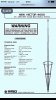
Look at the OUTSIDE of the Cone.
What do you see?
73
Jeff
I see it


Auto start phases canceled against each other, making the antenna unusable.


:sad:
compare with the GM....
is too obvious and gives me something show

Attachments
Last edited:
Although that is not the forum I was referring to about the testing at radio station KOLG, it is another interesting one. I was able to get them to understand what I described and it seemed like they were going to follow up with the same field testing I did to arrive at this conclusion. However, a year later nothing has been done. The concept is really quit simple. Perhaps too much so for some. Sweep the radials upwards on a 3/4 wave groundplane and you just made a "non apparent collinear".
:sad:
compare with the GM....
is too obvious and gives me something show
Unlike you, I've done exactly what you said and compared the Vector to the GM in the same location. Receiving one of the very first GM antennas to arrive in the USA. I was very pleased to find the GM had gain on the horizon that could not be distinguished from the Vector!
In other words the GM performed nearly identical to the Vector in distant contacts and is why it's on my roof today. Much easier to keep standing with our North East hurricanes and no loss in gain.
This is actually the first year I've been in this location where I have not had to climb back on the roof to repair antenna damage caused by severe storms and hurricane Sandy hit us with over 90 MPH winds!
There's a polarization wave reversal every half wavelength or quarter?. In a way it reminds me of my X-Dipole(Circular Polarization) antenna thread. The upturned radials would be radiating on the reverse wave by the time the positive/forward half wave/quarter reaches the top of the Vector. Correct me if I'm wrong but that's how I'm seeing it with my mind's eye.
dxChat
- No one is chatting at the moment.