• You can now help support WorldwideDX when you shop on Amazon at no additional cost to you! Simply follow this Shop on Amazon link first and a portion of any purchase is sent to WorldwideDX to help with site costs.

not seen improvement with TR24 modified

1iwilly

Sr. Member
Dec 7, 2008
813
588
103
62
ok, when I have R131 intact and vr12 wide-open look at pics of watts with mod-added then when I clip R131 you see the watts go up. with R131 intact I added a 1k ohm resistor to the middle leg TR24 and the other end of resistor back to board anyone knows why I'm not getting any increase with r131 intact and resistor added to tr24 ?? this is on my cobra 2000 gtl
 

Attachments

  • resistor.jpg
    resistor.jpg
    1.3 MB · Views: 8
  • no resistor.jpg
    no resistor.jpg
    1.4 MB · Views: 8
Last edited:

adding the 1K changes the response of the limiter but doesnt totally disable it.
cutting R131 does disable the limiter on AM.

i recommend removing that 1K and leaving TR24 alone as it is in the SSB path as well as AM and you really don't want to mess with the great SSB performance these radios have in stock form.

remember that without a scope to see the waveform, you really don't know whether that increased wattage is on the channel you are talking on, or if its just garbage from the negative peaks clipping and adding together on the wattmeter to show a higher number.
wattmeters are like dummy loads, they don't care what frequency the signal that comes into them is on.

turning up VR12 to the max is basically the same as removing R131.


try this, put the radio back to stock first.
now find R228 over near VR10. change R228 to a 1.2K resistor (1K will work if you don't have a 1.2K handy).

now solder a 1uF NON POLARIZED capacitor such as a ceramic or metal film cap from pin 9 of the audio amp IC to the junction of R194/D63/R228.

set your deadkey for about 2 watts for this to work best. definitely dont go above 4 watts deadkey.


still best to set VR12 with a scope after this mod, but if you just turn it up enough to see the watts increase but not all the way you should be ok.
This mod is courtesy of our own Exit13 and i'll stop hawking it once he tells me to stop LOL.
LC
 
thanks, loosecannon for the NPC is a 10uf, not 1 unless it has changed in the past 5 years. what about decreasing the value of r131 would that help ???


adding the 1K changes the response of the limiter but doesnt totally disable it.
cutting R131 does disable the limiter on AM.

i recommend removing that 1K and leaving TR24 alone as it is in the SSB path as well as AM and you really don't want to mess with the great SSB performance these radios have in stock form.

remember that without a scope to see the waveform, you really don't know whether that increased wattage is on the channel you are talking on, or if its just garbage from the negative peaks clipping and adding together on the wattmeter to show a higher number.
wattmeters are like dummy loads, they don't care what frequency the signal that comes into them is on.

turning up VR12 to the max is basically the same as removing R131.


try this, put the radio back to stock first.
now find R228 over near VR10. change R228 to a 1.2K resistor (1K will work if you don't have a 1.2K handy).

now solder a 1uF NON POLARIZED capacitor such as a ceramic or metal film cap from pin 9 of the audio amp IC to the junction of R194/D63/R228.

set your deadkey for about 2 watts for this to work best. definitely dont go above 4 watts deadkey.


still best to set VR12 with a scope after this mod, but if you just turn it up enough to see the watts increase but not all the way you should be ok.
This mod is courtesy of our own Exit13 and i'll stop hawking it once he tells me to stop LOL.
LC
 
no it's 1uF i promise, and dont use an electrolytic.
yes i know about Bills old NPC mod but never liked the sound of it much.
makes the response, well, mushy is the way i put it.

The mod i posted was invented by Exit13 and he put it on the forum in a thread called 130% modulation or something like that. as i said, you really need a scope to set it right, but either way, it will increase your positive modulation more than the negative.
sure, lowering the value of R131 will increase the modulation, but its the same thing as playing with VR12 for all intents and purposes.

any of these mods will cause the radio to swing up to its max potential, which is usually between 16 and 20 watts PEP for this chassis.
yes, you can get 25 by volting the final, but i never liked the sound of that either, as you are then only modulating the driver and to me it just didn't sound as punchy as when you are modulating both the driver and final.

OH! i forgot to mention that when doing that mod, Exit always recommended changing the AM regulator TR41 to a TIP41 or equivalent transistor because of the extra work you are asking the circuit to do.
LC
 
well there must be something choking my modulation look at pics change r228 to 1kohm resistor and a 104 disc cap to the junction you mention 2 watts dead key swinging to 2 1/2 watts

adding the 1K changes the response of the limiter but doesnt totally disable it.
cutting R131 does disable the limiter on AM.

i recommend removing that 1K and leaving TR24 alone as it is in the SSB path as well as AM and you really don't want to mess with the great SSB performance these radios have in stock form.

remember that without a scope to see the waveform, you really don't know whether that increased wattage is on the channel you are talking on, or if its just garbage from the negative peaks clipping and adding together on the wattmeter to show a higher number.
wattmeters are like dummy loads, they don't care what frequency the signal that comes into them is on.

turning up VR12 to the max is basically the same as removing R131.


try this, put the radio back to stock first.
now find R228 over near VR10. change R228 to a 1.2K resistor (1K will work if you don't have a 1.2K handy).

now solder a 1uF NON POLARIZED capacitor such as a ceramic or metal film cap from pin 9 of the audio amp IC to the junction of R194/D63/R228.

set your deadkey for about 2 watts for this to work best. definitely dont go above 4 watts deadkey.


still best to set VR12 with a scope after this mod, but if you just turn it up enough to see the watts increase but not all the way you should be ok.
This mod is courtesy of our own Exit13 and i'll stop hawking it once he tells me to stop LOL.
LC
 

Attachments

  • 20200815_204547.jpg
    20200815_204547.jpg
    1.9 MB · Views: 11
  • 20200815_204710.jpg
    20200815_204710.jpg
    1.5 MB · Views: 8
  • 20200815_204933.jpg
    20200815_204933.jpg
    1.2 MB · Views: 9
so i think i found the problem i just need to find the right info on my board i found a diode where R130 is where it feeds VR12 but on the original sams there is no R130 on the schematics and i don't have a D64 tied in with TR26 like on schematic look at pic does anybody knows what R130 should be ??
 

Attachments

  • 20200816_215424.jpg
    20200816_215424.jpg
    1.1 MB · Views: 11
  • 20200816_215458.jpg
    20200816_215458.jpg
    2.1 MB · Views: 11
  • 20200816_215557.jpg
    20200816_215557.jpg
    2.5 MB · Views: 9
  • 20200816_215734.jpg
    20200816_215734.jpg
    4.6 MB · Views: 9
Last edited:
if you look right at the top of VR12 you will notice that R130 is a diode.

if there is nothing there in that spot, then varying VR12 would not have any effect.

if you do find that there is nothing in the R130 hole, put a 1N4148 diode in there with the banded end toward the back of the radio.

there are many different versions of the same radio and factories changed things on certain runs because of many reasons. money being one of the big ones.
LC

EDIT: sorry just saw your pic, yeah, put a diode in the R130 hole.
 
ok put a diode in R130 spot i can control VR12 but mod is still low look a video i made where i have it with r131 cut and then with it back in circuit only a 1/2 swing that's what i'm trying to improve by the way i order some 105 cap waiting on them to come in
link to video=https://www.dropbox.com/s/nrv78kh007jli3y/20200817_112853.mp4?dl=0

QUOTE="loosecannon, post: 737668, member: 1368"]if you look right at the top of VR12 you will notice that R130 is a diode.

if there is nothing there in that spot, then varying VR12 would not have any effect.

if you do find that there is nothing in the R130 hole, put a 1N4148 diode in there with the banded end toward the back of the radio.

there are many different versions of the same radio and factories changed things on certain runs because of many reasons. money being one of the big ones.
LC

EDIT: sorry just saw your pic, yeah, put a diode in the R130 hole.[/QUOTE]
 
im not sure about your wattmeter readings.

i couldn't make the video play.

Could you tell me what the deadkey and swing numbers are?
with R131 intact.
does maxing out VR12 change the swing reading? to what number?
is that a peak reading bird meter or an average reading meter?

did you peak L38 with a modulated carrier or just with a deadkey.
it needs to be peaked with modulation applied.
 
wow i just check video playing ok ok so with r131 intact dead key1 1/2 watts swings to
barely 2 1/2 look a pic vr12 max out i always tune my radio with a 1000hz tone tru the mike bird is rms
oh, by the way, i order some 105 disc caps be here Friday to try out the NPC mod you mention

im not sure about your wattmeter readings.

i couldn't make the video play.

Could you tell me what the deadkey and swing numbers are?
with R131 intact.
does maxing out VR12 change the swing reading? to what number?
is that a peak reading bird meter or an average reading meter?

did you peak L38 with a modulated carrier or just with a deadkey.
it needs to be peaked with modulation applied.
 

Attachments

  • 20200817_195347.jpg
    20200817_195347.jpg
    2.8 MB · Views: 3
  • 20200817_195402.jpg
    20200817_195402.jpg
    2.9 MB · Views: 2
so on an average reading meter you should expect to see a 1.5x increase in power when modulated to 100%.

at 1.5 watts deadkey, that would be 1.5 x 1.5 which equals 2.25 watts.
your meter is reading correctly.

when you do the PPE mod i posted, you will be getting around 130 to 140% positive modulation, but your meter will still only swing up to 3 to 3.5 watts or so.

everyone who is talking about numbers like 16 to 25 watts of swing is talking about reading those numbers on a peak reading meter.
LC
 
i understand what you are saying but the reason i still say it's not right is because with the limiter clip i can adjust vr7 modulation meter but with it on vr7 wide open meter barely goes half-scale


so on an average reading meter you should expect to see a 1.5x increase in power when modulated to 100%.

at 1.5 watts deadkey, that would be 1.5 x 1.5 which equals 2.25 watts.
your meter is reading correctly.

when you do the PPE mod i posted, you will be getting around 130 to 140% positive modulation, but your meter will still only swing up to 3 to 3.5 watts or so.

everyone who is talking about numbers like 16 to 25 watts of swing is talking about reading those numbers on a peak reading meter.
LC
 
Last edited:
You're fighting two different battles.

You're playing with R131 and R130 / D501 - remember that with R130 - it is needed to keep TR24 working - but more off than on. Because R130 sinks power arriving from R131 and AMC / ALC amps - when you remove it, R131 turns on and keeps on - TR24 - ALL The Time. Means it's conducting, turned on.

When you remove R131 - you're turning off TR24.

R130/D501 - that area goes to VR12 - and because of D501 - TR24 will always be turned on just enough so you have limiter action.

Try this...
Cobra148R130R131R166R165.jpg
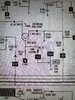
When the diodes banded end flows to VR12 (that pot in the graphic) your positive peaks still get limiter-action because of voltage drop and reverse biased diode - but because of the diode - heavier limiter action would occur because the Negative peaks get clamped thru the direct "valve" action D501 does.

So when you "jumper" the diode (Short it out) - your positive peaks and negative peaks are treated the same - above I use a 100 ohm resistor - just for example.

In the above graphic - you can even play with the resistors and the diode in it's directional ability to limit and compress - to achieve special effects some liken to compressional effects.

Your second battle is the POWER you use arrives from a different source.

R166, and R165 - form a voltage divider circuit that "taps" power from the AM Pass transistors (AM Regulator) so when you try to "tone down" TR 24 using R130 and R131 - you are still dealing with a large reserve of power from the AM Regulator that powers the AMC / Limiter.

R166, a 3.3K (Orange-Orange-RED) resistor and R165 - a 1.5K (Brown - Green - RED) - these form a divider and tap which pares down the signal (Audio and carrier) power the AM Regulator sends to the Driver and Final and sends it to TR24's junction of R130 and R131 and VR12

But the power you're dealing with (From AM Regulator) is part of the mess you're having issues with.

R130 and R131 can only do so much, so you'll need to change (Raise) the value of R166 to as much as 22K to help reduce limiter "clamping" action and enjoy your radio more. Just reduce the power arriving from the AM Regulator that powers your TR24 circuit.
 

dxChat
Help Users
  • No one is chatting at the moment.
  • @ Wildcat27:
    Hello I have a old school 2950 receives great on all modes and transmits great on AM but no transmit on SSB. Does anyone have any idea?
  • @ ButtFuzz:
    Good evening from Sunny Salem! What’s shaking?
  • dxBot:
    63Sprint has left the room.
  • dxBot:
    kennyjames 0151 has left the room.