• You can now help support WorldwideDX when you shop on Amazon at no additional cost to you! Simply follow this Shop on Amazon link first and a portion of any purchase is sent to WorldwideDX to help with site costs.

NPC for AM Transformer radios is HERE... Tubed, Solid State, etc. ANY high level TX

I guess it's a question of semantics, then.

To me, NPC was ONLY a way to keep the carrier alive. I didn't WANT it doing anything to my RF waveform.

When you look at the NPC mod for the series modulated transmitters (Galaxy, Cobra, etc), you'll see it hooks the audio waveform JUST above a diode.... That diode is going to cause problems with rectification of the AC component, and will cause problems with bleed as well... Just as pretty much any other circuit will.

What Shockwave is looking for with NPC is Assymetrical Modulation. That's too easy to accomplish nearly with phasing the microphone correctly! When you find the phasing on your mic that allows 125 percent pos peaks and 90 percent neg peaks, you THEN increase the audio to where you BARELY bump this circuit into conduction. You will then be at or over 150 percent positive peaks, and sounding like crap in nearly all receivers.... Especially when you are receiving on a simple diode detector. Add MORE distortion when the guy receiving has his noise blanker on.

This circuit is in current use on a pair of 4-1000s modulating a single 4-1000. That's a LOT of positive modulation capabilities, and it's being run as described above. You can't perform a lot of trickery in the transmitter itself to get assymetrical mod... You need to accomplish that via the modulator and (pre)driver to the audio stages.......

The problem you guys see with the rise and fall times of the mod waveform causing problems with distortion on the transmitted signal generally is indicative of the actual modulator (audio chip) running out of steam, or the transformer being undersized for the modulator.... It can also be caused by the wrong turns ratio for the transmitter, but not as bad.... I want to play with PAGING transformers, the 70V kind... Some are fairly cheap, have decent audio specs and will handle a hundred or more watts....

Anyway, this wasn't meant to GIVE you assymetrical modulation... That's something you get in the audio chain. This circuit is designed to eliminate the problems associated with running the carrier to 0 volts and the associated distortion with that.... It's not designed to be driven into conduction constantly.


--Toll_Free
 
  • Like
Reactions: NZ8N and Slowmover
Well, I guess at this point I'm kind of confused then. I would help if we could all see the results on a scope. That is, inject a test tone into the audio line, and show what happens to the modulation envelope when you exceed 100%.

I thought the basic idea behind NPC was that it _does_ give you asymmetrical modulation, though at the modulation stage rather than in the audio stage.

Your description (which I confess to not reading clearly at first) says that your mod just prevents the carrier from being pinched off. But you also say you don't do anything else to the waveform. Here's a really crappy drawing that shows two waveforms:

draw.jpg


The line through the middle of each is 0 volts. Both are intended to have the same positive peak amplitude (the positive peaks extend 3 lines from the 0 volt line).

The first shows the typical over-modulated carrier, with the negative peaks bottoming out at 0 volts.

The second is intended to show the same thing, except here we don't let the output bottom out: the negative peaks are prevented from touching the 0 volt line.

Is that what your circuit is meant to do? If so, then I would expect there would still be some distortion: the negative peaks still flatten out even though they don't touch.

Again, I apologize if I'm just being dense here.

-Bill
 
Your drawing shows exactly what I would expect this diode modification does. As long as that flat negative peak remains unfiltered, you have all the harmonic content of the first waveform still intact.
 
 
First of all... I’d like to thank TOLL_FREE for starting this thread. Technically, this is the BEST thread to appear on this forum in a long, long time !!!!


Secondly, I’d like to recommend that all of the posters to this thread look at this paper published by the National Association of Broadcasters. It concerns Modulation, Overmodulation, and Bandwidth on AM broadcast Stations. There is much space devoted to negative peak clipping and other audio enhancements. It is technically strong, but if I can understand it, you guys won’t have any problem.

http://www.nrscstandards.org/SG%20ref%20docs/AM_Mod_Overmod_1986.pdf

What I got out of this paper is that negative peak clipping (in broadcast stations, anyway) generates more splatter than regular overmodulation (carrier pinchoff). Also, if NPC is used, it should be implemented in the audio chain, and be followed by a sharp rolloff low-pass filter (the type of circuit that MrSuburban described and uses on his Johnson Valiant). Finally, a "protection clipper" should be installed in the rf output circuit to limit any negative peak overshoot that might cause carrier pinchoff. The circuit that TOLL_FREE posted fits this requirement completely.

Lastly, speech clipping is an effective method for increasing AVERAGE modulation and making a radio sound louder on-the-air. Some early tube rigs (Browning Eagles and Sonar CBs, in particular), utilized speech clipping, and because of this, are still great performers, even today. In solid-state CBs, only the Uniden "858" rigs had speech clipping circuits, and they worked so well that they were banned by the FCC in 1979. These radios included the Cobra 21, 25, 29, 89, 138, and 139 in the XLR series. Identical chassis were marketed by Courier, Realistic, President, Robyn, Sears, Teaberry, and others. The problem is that speech clipping introduces distortion that removes much of the "NATURAL" sound of the audio. Supposedly, NPC also raises the average modulation, but has audio with a much more natural sound.

I run 858 SSB radios on my base exclusively, and after reading MrSuburban’s post, I decided to try his mod on my TRC-457. I jumpered the positive peak limiting diode (D21) with an spst relay so I could switch the mod in and out. On a ‘scope, the positive mod peaks showed a definite increase, but since there are no other local stations around here, I couldn’t get an audio check to see if I sounded louder (and clearer) with the NPC mod or not.

Maybe LOOSECANNON can try this on his 139XLR and post the results.

This type of clipping circuit can be easily added to any radio. If you want specific info, let me know.

Sorry that this was so long-winded. Hope it made sense.


- 399
 
Last edited:
  • Like
Reactions: Slowmover
unit_399 [FONT=Verdana said:
What I got out of this paper is that negative peak clipping (in broadcast stations, anyway) generates more splatter than regular overmodulation (carrier pinchoff). Also, if NPC is used, it should be implemented in the audio chain, and be followed by a sharp rolloff low-pass filter (the type of circuit that MrSuburban described and uses on his Johnson Valiant). Finally, a "protection clipper" should be installed in the rf output circuit to limit any negative peak overshoot that might cause carrier pinchoff. The circuit that TOLL_FREE posted fits this requirement completely.[/FONT]

The 3 diode modification does not clip, does not compress, and is not followed by any filter. It does nothing more then sustain a certain value of carrier and has no real effect on reshaping the flattened waveform. If you want to know exactly why the diode circuit does not work, read this http://www.w8ji.com/Johnson audio mods.htm Scroll down to the "Diode super modulation modification" and read what Tom W8JI says.

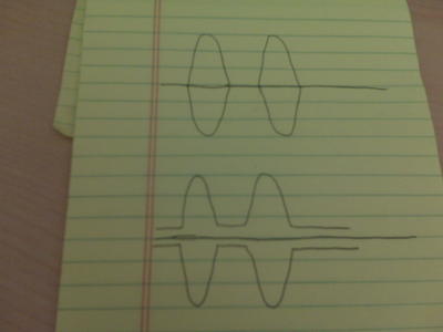
Here is what is important "1.) Going to zero-carrier is actually not what causes splatter or excessive bandwidth. The slope of waveform abruptly changing, going in a new direction towards a straight line, causes the signal to get wide. It's really a "Fourier problem", where the rapid change in slope requires high-order harmonics to produce the waveform".

Without reshaping of the slope I argue nothing has been accomplished in terms of spectral purity. What Tom says about a tetrode amp is an entirely different problem with this mod that does not apply in our case. Sadly, it looks like this mod will not keep your TX clean at modulation levels in excess of 100%.
 
The 3 diode modification does not clip, does not compress, and is not followed by any filter. It does nothing more then sustain a certain value of carrier and has no real effect on reshaping the flattened waveform. If you want to know exactly why the diode circuit does not work...

.

That is my point exactly. The three diode will only serve as a "protective clipper" to prevent any negative peak overshoot from causing carrier pinchoff.

Splatter is caused by the clipping process, and by carrier pinchoff. If we implement the clipping in the audio chain and follow it by a lowpass filter, we eliminate the harmonics generated by the clipping process. If we follow that by installing the circuit described by TOLLFREE in the rf chain, we can eliminate the harmonics generated by overmodulation. This might not be "spectral purity" as you think of it, but it is damn close.

- 399
 
Anyone consider the extra modulator power needed to facilitate use of the 3 diode ultramodulator?

Ya can't hook this thing to any commercial ham tx and expect it to do anything useful.
 
That is my point exactly. The three diode will only serve as a "protective clipper" to prevent any negative peak overshoot from causing carrier pinchoff.

Splatter is caused by the clipping process, and by carrier pinchoff. If we implement the clipping in the audio chain and follow it by a lowpass filter, we eliminate the harmonics generated by the clipping process. If we follow that by installing the circuit described by TOLLFREE in the rf chain, we can eliminate the harmonics generated by overmodulation. This might not be "spectral purity" as you think of it, but it is damn close.

- 399

Unless I've completely overlooked something, this circuit does not provide any clipping whatsoever. It does nothing more then hold the carrier alive just as the circuit description on the The AM Window says. It claims no clipping action at all.

W8JI carefully explains how splatter has nothing to do with RF cutoff and has everything to do with the rise time and fall time into and out of the of the cutoff point. When the transmitter is cutoff, there is no power and no interference. When the angle of the waveform changes abruptly and with sharp corners, you have splash.

To the best of my knowledge overmodulation causes interference that is harmonically related to the modulation frequencies and not RF frequencies. This places the interference very close to the fundamental frequency and means normal bandpass or low pass RF filters will not remove it. It must be done after the clipping of the AF.
 
  • Like
Reactions: NZ8N
Anyone consider the extra modulator power needed to facilitate use of the 3 diode ultramodulator?
Ya can't hook this thing to any commercial ham tx and expect it to do anything useful.
Exactly!
And that's why the "Tall-Ship" AM'ers use a modulator that is at least as powerful as the rig's input power. You need that extra modulation headrooom to gain any benefit from the 3-diode negative peak clipper. And this is why all broadcast transmitters follow the same rule. My BC rigs run a pair of 4-400's modulated by another pair. Those rigs can do 125% positive easy, (if not way more). But, we do the peak streatching upstream in the audio with an Orban, or a Dorrough processor.

I run a 3-diode negative peak clipper (or "negative cycle loading") in my 813 rig: a pair of 813's modulated by a pair of 810's. 700+W of audio modulating 700W of carrier. I get about 135% positive peaks out of that rig. Unfortunately, there are artifacts generated by this circuit, which some listeners find unpleasant. You can't get something for nothing. :sad:
 
  • Like
Reactions: NZ8N
Yes, that is D8. If you want to LOWER the deadkey of the radio, and still keep the same audio in proportion, you would ADD diodes in SERIES to this one, and D1 and D2 would still be put at each end of the entire chain.

I lived in Colorado Springs for a short time, up in Cascade, too.... Used to go back a couple times a year, beautiful country!

Hope that helps.

--Toll_Free

Hello Toll_Free thanks for you xmas gift to the community,I found this circuit from Handy Andy long while ago on my internet travels
 

Attachments

  • AsymetricalAMinstall1.jpg
    AsymetricalAMinstall1.jpg
    52.8 KB · Views: 226
  • AsymetricalAMinstall.jpg
    AsymetricalAMinstall.jpg
    110.8 KB · Views: 265
Hi Ed,

Negative cycle loading does work but the modulator needs to be able to work into a different impedance in the negative direction than the positive direction as the neg cycle resistor is in parallel with the load of the RF final. I'm sure this will raise hell with inverse feedback found in better modulators.

There are plenty of positive peaks to be had with just proper modulation transformer ratios and decent audio bandwidth.

Yeah the old P.E.P. wattmeter will go nuts at 200% positive. So will distortion in most receivers.

JI is correct about the abrupt waveform containing audio harmonics and generating more off channel products.


JI is all wet on his take of how a tetrode is high level modulated. He is ignoring the screen voltage dynamic. RCA, Gates, McMartin and quite a few others violated his premise in their tetrode broadcast machines.

JI is also off the mark claiming he can get 120% positive out of a Valiant with the factory 4:1 modulation transformer and common supply.


Exactly!
And that's why the "Tall-Ship" AM'ers use a modulator that is at least as powerful as the rig's input power. You need that extra modulation headrooom to gain any benefit from the 3-diode negative peak clipper. And this is why all broadcast transmitters follow the same rule. My BC rigs run a pair of 4-400's modulated by another pair. Those rigs can do 125% positive easy, (if not way more). But, we do the peak streatching upstream in the audio with an Orban, or a Dorrough processor.

I run a 3-diode negative peak clipper (or "negative cycle loading") in my 813 rig: a pair of 813's modulated by a pair of 810's. 700+W of audio modulating 700W of carrier. I get about 135% positive peaks out of that rig. Unfortunately, there are artifacts generated by this circuit, which some listeners find unpleasant. You can't get something for nothing. :sad:
 
  • Like
Reactions: NZ8N
Hi Ed,

Negative cycle loading does work but the modulator needs to be able to work into a different impedance in the negative direction than the positive direction as the neg cycle resistor is in parallel with the load of the RF final. I'm sure this will raise hell with inverse feedback found in better modulators.
Interesting observation. I completely overlooked that aspect. Now why would the neg. cycle load resistor affect NFB, when that resistor is not in circuit except during neg. cycle cut-off?

There are plenty of positive peaks to be had with just proper modulation transformer ratios and decent audio bandwidth.
Agreed. Don't forget your phasing.

Yeah the old P.E.P. wattmeter will go nuts at 200% positive. So will distortion in most receivers.
Positive opeak stretching can only go so far before you start to overload simple diode detectors. I believe that a simple diode detector will start to distort at about ~130-140% positive. (Thus the broadcast standard of maximum 125% positive.)

JI is also off the mark claiming he can get 120% positive out of a Valiant with the factory 4:1 modulation transformer and common supply.
Timtron (Tim, WA1HLR) has promoted the concept of "Turbo-modulation", where the standard mod transformers in Heath and Johnson rigs are rewired as an autotransfomer. He claims 120% positive peaks with this mod. Having several DX-100's and Apaches, I haven't tried it.
 
  • Like
Reactions: NZ8N
VA3ES, the Cobra 29 and other transformer driven modulation schemes in most CBs is ALREADY configured as an autotransformer..... Which is what timtron is advocating doing.

W8JI is off his rocker on a lot of things. There's a reason he does private consulting now, and doesn't have a 'real job', so to speak... He's made his millions from the AL amplifier series, and now doesn't have to put up with peoples bullshit... As such, he pretty much comes up with his theories and tells everyone who doesn't agree with him that they are full of crap and to stuff it. I've been watching the argument and war between w8ji and AG6K for years... it's funny, and makes channel 19 look stupid!

THAT BEING SAID, he is correct about some of the things in his article about 3 diode limiters, peak loading, etc.

Anywho, the circuit is here, people can use it if they want... It's getting to the point where people are arguing about what to call it, rather than discussing what it can and can't do... We got what it can and can't do. It CAN'T make up for an idiot behind the controls. It CAN, as I pointed out, using proper processing and audio equipment, make a LOUD AS HELL radio (station).

--Toll_Free
 
  • Like
Reactions: NZ8N

dxChat
Help Users
  • No one is chatting at the moment.
  • @ Wildcat27:
    Hello I have a old school 2950 receives great on all modes and transmits great on AM but no transmit on SSB. Does anyone have any idea?
  • @ ButtFuzz:
    Good evening from Sunny Salem! What’s shaking?
  • dxBot:
    63Sprint has left the room.