• You can now help support WorldwideDX when you shop on Amazon at no additional cost to you! Simply follow this Shop on Amazon link first and a portion of any purchase is sent to WorldwideDX to help with site costs.

NPC for AM Transformer radios is HERE... Tubed, Solid State, etc. ANY high level TX

Well, I guess at this point I'm kind of confused then. I would help if we could all see the results on a scope. That is, inject a test tone into the audio line, and show what happens to the modulation envelope when you exceed 100%.

I thought the basic idea behind NPC was that it _does_ give you asymmetrical modulation, though at the modulation stage rather than in the audio stage.

Your description (which I confess to not reading clearly at first) says that your mod just prevents the carrier from being pinched off. But you also say you don't do anything else to the waveform. Here's a really crappy drawing that shows two waveforms:

draw.jpg


The line through the middle of each is 0 volts. Both are intended to have the same positive peak amplitude (the positive peaks extend 3 lines from the 0 volt line).

The first shows the typical over-modulated carrier, with the negative peaks bottoming out at 0 volts.

The second is intended to show the same thing, except here we don't let the output bottom out: the negative peaks are prevented from touching the 0 volt line.

Is that what your circuit is meant to do? If so, then I would expect there would still be some distortion: the negative peaks still flatten out even though they don't touch.

Again, I apologize if I'm just being dense here.

-Bill

Bill,

PERFECT representation of what the scope shows.

As long as you don't hammer the modulator, you can get as loud as it's capable of.

Again, this circuit isn't for idiots. ANY TRANSMITTER CAN BE MADE TO SOUND LIKE SHIT!

:)

BUT, thanks for the clarification, with actual pictures.

What nobody is looking at is this: When you 'baseline' the carrier by overmodulating and then NOT keeping the carrier alive, you're actually creating pulsating DC. And we ALL know what happens when you halfwave rectify an AC signal..... It creates harmonics that are INSANE.... Those of us old enough to remember 'xtal markers' can relate to this.

--Toll_Free
 
  • Like
Reactions: NZ8N
 
First of all... I’d like to thank TOLL_FREE for starting this thread. Technically, this is the BEST thread to appear on this forum in a long, long time !!!!


Secondly, I’d like to recommend that all of the posters to this thread look at this paper published by the National Association of Broadcasters. It concerns Modulation, Overmodulation, and Bandwidth on AM broadcast Stations. There is much space devoted to negative peak clipping and other audio enhancements. It is technically strong, but if I can understand it, you guys won’t have any problem.

http://www.nrscstandards.org/SG%20ref%20docs/AM_Mod_Overmod_1986.pdf

What I got out of this paper is that negative peak clipping (in broadcast stations, anyway) generates more splatter than regular overmodulation (carrier pinchoff). Also, if NPC is used, it should be implemented in the audio chain, and be followed by a sharp rolloff low-pass filter (the type of circuit that MrSuburban described and uses on his Johnson Valiant). Finally, a "protection clipper" should be installed in the rf output circuit to limit any negative peak overshoot that might cause carrier pinchoff. The circuit that TOLL_FREE posted fits this requirement completely.

Lastly, speech clipping is an effective method for increasing AVERAGE modulation and making a radio sound louder on-the-air. Some early tube rigs (Browning Eagles and Sonar CBs, in particular), utilized speech clipping, and because of this, are still great performers, even today. In solid-state CBs, only the Uniden "858" rigs had speech clipping circuits, and they worked so well that they were banned by the FCC in 1979. These radios included the Cobra 21, 25, 29, 89, 138, and 139 in the XLR series. Identical chassis were marketed by Courier, Realistic, President, Robyn, Sears, Teaberry, and others. The problem is that speech clipping introduces distortion that removes much of the "NATURAL" sound of the audio. Supposedly, NPC also raises the average modulation, but has audio with a much more natural sound.

I run 858 SSB radios on my base exclusively, and after reading MrSuburban’s post, I decided to try his mod on my TRC-457. I jumpered the positive peak limiting diode (D21) with an spst relay so I could switch the mod in and out. On a ‘scope, the positive mod peaks showed a definite increase, but since there are no other local stations around here, I couldn’t get an audio check to see if I sounded louder (and clearer) with the NPC mod or not.

Maybe LOOSECANNON can try this on his 139XLR and post the results.

This type of clipping circuit can be easily added to any radio. If you want specific info, let me know.

Sorry that this was so long-winded. Hope it made sense.


- 399

If you REALLY want to increase the complete talk-power on those units (I've been working with the 858 Unidens and the processors / clippers in them for about 25 years), add a diode or two to the POSITIVE side. This will still allow for some amount of clipping (good), but will INCREASE the positive side.

OR, keep a SILICON rectifier diode on the positive side, and a germanium or shottkey on the negative side. I did just this in a Lou Franklin clipper, and it make it about twice as loud: Not bad when you consider the processor gets the same compliments by itself!

Have any other questions on them, lemme know. Since that radio uses a TRANSFORMER to couple the AM waveform to the DC bus, you can also use this circuit to eliminate baselining the carrier.

THIS is how this circuit SHOULD be implemented. HOWEVER, it CAN be used with the AMC in the radio, as long as you don't disable it, destroy it, or otherwise cause problems in the AMC arena.... Coupled with the 3 diode peak limiter, it will REALLY help out.


--Toll_Free
 
I'll have to get a camera out that actually takes a decent pix of my scope.

The cam phone I have does OK, but gets REALLY wavy lines through it. The problem is I use nearly ALL HID lights throughout the house. A 45-65 watt will put the light out that a 150-200 watt incandescent does, and doesn't cause the headaches that the floro does. Nor do they cause the problems with audio hum and ZZZZZZZot sounds that floro ballasts do.

Maybe I can do one in the dark, just the scope on. Would look eerie, but I'll give it a shot. The waveform looks just like the drawing presented before, however... BUT, the Cobra 2x chassis audio amp chain WILL cause triangle wave distortion to the audio signal before the modulator clips..... I haven't gotten that deep into the modulator after performing this mod... Paying radios came across the bench so I had to shelf this project for a week or so.


I've got another iteration of it that uses a transistor I'm working on, but who knows how that will work. Will give variable carrier and the NPC that people are confusing with Assymetrical modulation.

--Toll_Free
 
  • Like
Reactions: NZ8N
Interesting observation. I completely overlooked that aspect. Now why would the neg. cycle load resistor affect NFB, when that resistor is not in circuit except during neg. cycle cut-off?

The final's load and the negative cycle load are in parallel. The negative cycle loading is there throughout the neg cycle. The postive cycle only sees the final's load.

Positive opeak stretching can only go so far before you start to overload simple diode detectors. I believe that a simple diode detector will start to distort at about ~130-140% positive. (Thus the broadcast standard of maximum 125% positive.)

Common diode detectors start distorting above 30%. They really fall apart above 125%. Some distortion is tolerated as a tradeoff for improved SNR.

Timtron (Tim, WA1HLR) has promoted the concept of "Turbo-modulation", where the standard mod transformers in Heath and Johnson rigs are rewired as an autotransfomer. He claims 120% positive peaks with this mod. Having several DX-100's and Apaches, I haven't tried it.

Timtron knows what he's doing. The "turbo" connection for mod transformers along with inverse feedback to make the modulators act more like triodes as far as load impedance really wakes those rigs up.
 
  • Like
Reactions: tecnicoloco
If you REALLY want to increase the complete talk-power on those units (I've been working with the 858 Unidens and the processors / clippers in them for about 25 years), add a diode or two to the POSITIVE side. This will still allow for some amount of clipping (good), but will INCREASE the positive side.

OR, keep a SILICON rectifier diode on the positive side, and a germanium or shottkey on the negative side. I did just this in a Lou Franklin clipper, and it make it about twice as loud: Not bad when you consider the processor gets the same compliments by itself!

--Toll_Free

I have a TRC-457. I'm interested in the two mods above to the diode pair/clipper that comes stock. What net effect would adding a diode or two in series with d21 (positive side on my radio) or replacing the stock diode @ d22 (negative side) with a schottky have? I assume you'd create favorable conditions for higher positive peaks while still keeping the negative peaks in check? (Asymmetric modulation instead of ~100%)

Anyone try this on an 858 radio's clipper? I have a schottky diode sitting right here...
 
What is this supposed to do in the radio
if you don't mind me asking and would this
work in a Texas Ranger 936ffc.
 
I finally remembered about this mod and built the circuit on a perf board. Hooked it up in a Cobra 25 on the D10 diode (anti-spike), ran the ground and B+ and it did nothing more to my audio as herd from others around town. Not louder, not more.
Its possible I did something wrong but this is so simple I know I didn't do it wrong.

Whats up with this?
 
I put it in my 29 yesterday in combo with the J36 mod. I ended up with a about 33 ohm resistor. 3, 100ohm, 1W. Half watt resistors got hot! I now wanna try the LM317 supply
 
Timtron (Tim, WA1HLR) has promoted the concept of "Turbo-modulation", where the standard mod transformers in Heath and Johnson rigs are rewired as an autotransfomer. He claims 120% positive peaks with this mod. Having several DX-100's and Apaches, I haven't tried it.


Timtron knows what he's doing. The "turbo" connection for mod transformers along with inverse feedback to make the modulators act more like triodes as far as load impedance really wakes those rigs up.

I have to thank Tim for this tip. Not only did it save my old DX-100, that rig never talked better than it did with an old TV power transformer, wired in the "Autotransformer Turbo Mode". Adding other windings into the mix, like the 6.3 and 5.0 volt filament windings, made it possible to dial in a near prefect impedance match with this repurposed modulation transformer.

When I got long winded and smoked the stock transformer, it looked like it was going to be difficult to replace. I searched for some time before stumbling onto Tim's article regarding how to rewire an old power transformer, as a modulation transformer. To say I was pleased with the results of his idea, would be an understatement.
 
This is what Steve has to say about this mod...

Just a refresher...
upload_2021-3-19_20-29-59.png

Now, I'm not here to do any bashes, battling or argue the finer points.
You've already got some of my work posted here as variants.
So I as like Toll-Free - ,lay no claims to the mod, only to try and break it down,
So even I could understand it.
In the CB Tricks days, I did up a thread about Asymmetrical Mods, both in method and ways others have already started doing to try to make more "swing". The above was included in that thread.

Much of what was in that thread has already been discussed in other threads here - so all I'm trying to do is add some more "latest news" as I have time for.

Here's an excerpt...


Because what the above does, is similar to what we have been applying in other portions of this thread.

The best way I can describe this event is similar to a stream of water flowing out of a waterfall into a pool - if you got a waterwheel and inserted it into the falling stream - you capture energy as is falls,(potential) the weight of the water (kinetic) as well as it's length of fall before it's used (momentum) - this concept needs to be kept in mind when I elaborate.

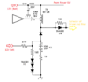
The output of the modulation transformer - before D8 is very complex and contains negative going energy that can cause cutoff - so the use of D8 as a spike diode is for the purpose of reverse bias prevention. It does nothing else - it removes energy that is flowing in the wrong direction - and that information is lost. All that is left is a DC bias (and forward Audio components) being sent to the Driver and Final in it's place.

•As points to remember

•The use of the Resistor - Divider Network keeps the Capacitor charged to 1/2 the supply rail that the Audio Amp uses and follows the output "sags" that occur when you are using the Limiter. If you so choose, these resistor values can more closely match your limiter "divider" supply as for limiter action will affect the output of the Reactance Modulator.
•The Dividers power capacity is dependent of the resistor values so it will charge at a slower rate using higher resistor values - adjust accordingly when you are working in the proper bias values to allow the "soft clipping" when the Modulation levels are heavy - for the Average and RMS power levels will appear to "drop" - so the use of the right resistance helps to provide the lower-range (as in the bottoming out of the Capacitors reserve charge before it can recover similar in operation to the AM Regulation sections "Gain Cell" capacitor).
•Please take heed: This tap section does not need D3! You already are tapping this area for power anyways, because where the "keep alive" circuit goes, is to the Asymmetrical Resistor TEE's shown earlier as Variants - in the above graphic, these apply as Variants 2 or 3.
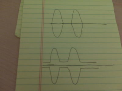
  • Let's take the focus off of D8 for the moment; think of the output of the transformer as that falling stream of water - most goes straight out - has a positive flow towards the Driver and Final. But as always, there is a DISPLACEMENT of energy that is demanded back through the Output of the Reactance Modulator - so the stream going out is not always "steady" there are "Bursts" of energy that force the water out at a greater pressure (Voltage) and in doing so, the remaining Volume (Current) is reduced because of the capacity the water channel is in size (AWG gauge as well as Reactance in Turns of the coil) so there will be moments of NEGATIVE pressure that seems to make the water stop or CAVITATE - which is the reason for D8 - to prevent this Cavitation from damaging the Driver and Final.
So, the output of the tap, has not been "tied" to anything except output - so it's negative energy can be captured in a capacitor and stored for brief moments.

This is what I'm referring to a the negative swinging energy that is being converted into a pool of energy that is captured - we can't do anything with the audio information within the waveform being so negative that applying it would cause severe damage - so it's energy is then stored - converted into a working bias...

That is the purpose of the Diode strapped parallel across the storage cap. So as this Negative Energy tries to extract itself from the capacitor - that energy is lifted/pushed into the falling level of power that this negative spike is inducing into the output side of the circuit. So the power level falls - if only briefly. The Diode prevents the capacitor from getting damaged by reverse bias current at the output of the Modulators own tap. The twin Resistor divider then provides a replenishment to the pool of energy we want for the capacitor to have to pull from for the next negative going spike.

Remember the Limiter discussion - and how the Diode only conducted when the level of audio (average or RMS - Peaks too) drops below a set point that was set by a resistor divider network. This energy was stored in a series of capacitors to act as a reservoir or pool in which the Limiter Transistor used and took energy away (audio) from the Mic amps input line from the microphone as a means to equalize a potential difference between the Limiters Base and Capacitors connected to it and a ground potential - it uses negative energy as a means of power, as a limiter; to limit or pull power from another source - in this case - the Audio from the Microphone.. Power can be present for a moment of time before being bled off from by a resistor and capacitors (bank) to feed this energy back into ground or pull from a feedline containing Microphone audio that is going into the Mic Amp - the resistor in the circuit just after the diode along with the values of the capacitors - developed the timing as well as the energy levels the Limiter worked in.

The above circuit - and it's location in the circuit - output from the Modulation transformer - allows us to tap into this negative-going energy as a means to generate an OFFSET voltage that can power another device or generate an increased bias potential to help remove or prevent - cutoff - by summing the voltage present - storing it in a capacitor - and then when the energy potential difference - the power level in the output of this circuit at the junction of the storage capacitor and D3, is less than the energy stored in the capacitor - can allow it, that energy- to be released back into the audio line.
  • But that is why we don't need D3 in the circuit, we take it out because of both our limiter divider, as well as our Resistor TEE are positioned to provide a transfer of power into the TX chain for reserve energy that can be imposed onto the RF as it tracks down the chain and has audio applied to it from each collector the TX Chain has from the starting - injection - point we chose.
This is a lot like how a Limiter or Automatic Noise Limiter would function. It blanks out a negative-going power spike by prevention of the reverse-bias condition by storing the energy into a capacitor and then releasing it back into the Audio BIAS line that goes to the Driver and Final. In he ANL system, this is a similar function as it "blanks" out the noise spike using the energy stored in the capacitor.
What the Mod does is utilize the Spike diode as the means to provide the forward power, with the negative-swing energy that is part of the Phase Modulation occurring in the transformer - the audio frequency energy - as it's vectors - that would swing negative - and damage the Final. Now - is given a chance to be restored as some captured energy, although it's frequency component is gone, the DC shift the energy has in the vector is kept as part of the charge that the capacitor takes in BELOW the reference voltage and even below the Board Ground.

.
The above is what I saved as quoted from my work in those pages about this mod.

Unfortunately much of the original work is now lost.

Occurred in 2016 when CB Tricks Forums folded - so much of the above is archaic compared to todays knowledge of the mod,

But I post this as reference to know that as the time of posting the works - which was an on-going process, That work started in 2013 as a means to preserve the methods that people use of and for swing and many of these mods were creative as well as unique,

But in the wrong hands of an abusive operator, they can inflict damage not just to the equipment - but to interfere with others - so to see this thread get bumped - I also reviewed the thread to find some of my own works involved,

No need to worry, I'm only here in an effort to follow along and perhaps offer more methods that have used the above circuit in some way.

So I only post this as a place to start from - for there have been several years if not nearly a decade of discussions and designs that evolved from these as variants.


As time permits me,
I will be adding more from my archives...​
 

Attachments

  • upload_2021-3-19_21-8-51.png
    upload_2021-3-19_21-8-51.png
    1.7 MB · Views: 36
  • AsymmetricMods.txt
    282.4 KB · Views: 28
Last edited:
I'm going to leave this here, for what this was a part of the Asymmetrical post thread that was from CB Tricks days, so Bennie - here's what I was trying to post that day...
upload_2021-5-14_22-14-36.png
TENATIVE​

The Rest of this - to explain, is not difficult to grasp, just lengthy.

This uses D8 as your standard clipper diode, but note the 100 ohm "swamp" resistor - that lessens the effect of the direct clip, this will generate some "FM" or Phase modulation, but the rest of the circuit needs to be considered for, many of you may recognize it.

Firstly, a "trickle" bias is created using the 12 V power feed, into a 270 ohm resistor thru a 150 ohm resistor working as a divider - with a holding voltage of 1.5 volts approximately to be applied to the output of the Transformer. In using 3 Diodes and their Forward Voltage drop - this voltage is applied to the output as a means to prevent negative potential from damaging the Collectors.

The "back to back" Electrolytic pair form a Gain cell with a 15 ohm resistor to offer a means to store and "pulse" the negative clipped energy thru the Diode to the Modulator. As the negative peaks allow - the energy stored in this gain cell can be applied to offset the missing audio - you may see a clipping effect, but the audible distortion should also be reduced by a considerable margin.
  • When the Audio amp swings above and below it's 1/2 supply rail - the output cap transfers this - in both a positive and negative swing - the Audio peaks are sent thru the transformer, a negative swing pulse can be generated, which - if this was not a concern you'd simply run the output of the transformer straight into the Collectors.
  • You can, but the Collectors won't tolerate the negative bias and voltage peaks - it creates a reverse biased condition.
The Clipper Diode - D8 prevents this, but in the process you can lose a lot of fidelity from the crossover distortion - the other part of the audio waveform that is clipped. The purpose of the 100 ohm Resistor ACROSS D8 is to help with the Crossover distortion biasing that the Diode could affect.

What we are doing here, is pushing up from 50% of the audio Signal - into more of a 60~70% recovery of the Audio signal - by raising the DC Bias and lengthening the forward conduction condition D8 can now provide.

Granted this may look more like it would be a clipper with a spike diode - but you can "tailor" the injection of the Gain Cell power to some degree of effect by using a resistor to lessen the effect of direct clip and multiplication that can occur, we place Rt as a means to control how much current and voltage can be injected into the D8's forward conduction.

upload_2021-5-14_22-8-41.png
Tentative
(This means use at your own risk)

We can also place more emphasis of Audio compression by changing how much Bias is present by allow more of the negative swings to exert more of their influence, onto the Gain Cell and the Bias Drive by adjusting how much Bias is present and allow the 3 Bias Diodes More control of the "floor" of this Gain Cells' ability to inject power stored in itself - back to the Collectors.


Attachments

  • upload_2021-5-14_21-28-17.png
    upload_2021-5-14_21-28-17.png
    55 KB · Views: 11
Last edited:

dxChat
Help Users
  • No one is chatting at the moment.
  • @ Wildcat27:
    Hello I have a old school 2950 receives great on all modes and transmits great on AM but no transmit on SSB. Does anyone have any idea?
  • @ ButtFuzz:
    Good evening from Sunny Salem! What’s shaking?
  • dxBot:
    63Sprint has left the room.
  • dxBot:
    kennyjames 0151 has left the room.