Radio was working fine ,turned it on the next day and now it has no tx power on AM or SSB ,receive still works fine ,no watts at all coming out but if I hook up another radio next to and listen I can here the radio key up on the monitor radio anybody have any ideas

You are using an out of date browser. It may not display this or other websites correctly.
You should upgrade or use an alternative browser.
You should upgrade or use an alternative browser.
-
You can now help support WorldwideDX when you shop on Amazon at no additional cost to you! Simply follow this Shop on Amazon link first and a portion of any purchase is sent to WorldwideDX to help with site costs.
-
Retevis is giving away a new RA89R for Father's Day! Click Here for more info!
Old uniden Grant PC409ac board
- Thread starter CBC544
- Start date
there is an electrolytic cap on these boards that, if it shorts, will kill all the transmit power.
with these radios getting older, the caps are starting to dry out and this can happen.
i think its C95, but its been a long time and i cant quite remember.
to check it, remove it from the chassis, and test it with an ohmmeter.
it should read open connection, AKA "no connection".
if it reads "0" ohms or "shorted", then replace it.
the other thing to try is to test the driver and final transistors to make sure they are working.
unsolder the leads from both transistors and lift them so they are not making contact with the PC board.
using the diode function on a digital multimeter, check to make sure they are not shorted or burned open.
google "testing semiconductors with a DMM" to find the instructions on how to do this test.
its easy and the instructions are all over the web.
good luck,
LC

Thanks
Hey Loose Cannon,
I owe you a Beer ! I just got 3 of these on FleaBay and the first 2 I tried no transmit ! Flung open the cover of the prettiest one and changed c95 and it transmits ! I might have found this eventually myself because I am replacing all the Electrolytic caps in all 6 of my grants (3 exports) but it is great to have this up and working right away, so THANK YOU !
you are very welcome.
congrats on the new radios.
be nice to them. the MB8719 PLL chip that is in those radios is VERY sought after and very hard to find. can you say expensive?!
i am a huge proponent of replacing all the electrolytics in these old radios, and you will find that they work AWESOME once you do it.
make sure you use 16 volt or higher caps. the ones rated at 10 volts never should have been used.
remember that the radio might need an alignment after you do this, as the values of the new caps will be a bit different than the old ones.
i wrote up a tutorial on how to align a 148GTL which is very close to the same as your grants.
you can find it by searching this forum.
not sure what i titled it though, sorry.
here are a few upgrades you should do when you are replacing all the caps.
these are not "peak and tweak" mods that mess up the radio, they are parts upgrades that make it work better.
replace Q41 with a 2N6487 or an NTE152.
this is the AM power reg. and the stock ones are underrated for what they do.
replace the main filter cap (i think its C172) with a 2200uF or 3300uF 25 volt cap.
this will give the radio some better headroom during modulation peaks.
replace C18 with a 680-1000uF cap.
this filters the mic line better and keeps the radio from squealing if you turn up the audio.
you can speed up the AMC attack time by replacing C109 with a 3.3uF cap.
replace C181 with a 1000uF cap. better filtering for the power supply.
the 2SC2999 receive mod works great in this chassis, and i highly recommend it.
you can buy the kits on ebay pretty cheap, as the 2999 can be hard to find on your own.
the diodes used are shottky barrier diodes. 1n6263 or NTE583.
replace Q14 with the 2SC2999 and replace D1, D2, D21, and D22 with the shottky diodes.
they are the AM detector and the noise blanker diodes.
there are many more mods for this chassis, and ive probably tried them all.
most of the modulation mods are actually worse than the radio is stock.
after trying all the mods, i now run my base station stock with a D104 silver eagle and it sounds great.
in the mobile i will remove R131 which disables the AM limiter but leaves the SSB circuits alone.
never remove or modify TR24 as it will cause SSB distortion.
changing R124 and 126 like all the google mods say will just make the radio want to squeal and make the audio sound muffled.
good luck with those radios and feel free to PM me if you have specific questions.
can you tell i love these radios? LOL
LC
oh, and i drink Sierra Nevada IPA. LOL
Thanks loosecannon!
I just wanted to add to this old thread and thank you big time for helping me with the same problem. I'm currently in-process of restoring an old Grant with the same board and same C95 issue. This was a radio that was headed for the dumpster for sure. Fully modified and I would guess circa 1980. It took a little time but I finally got c95 out and tested it and yes, it was bad. The only bad part of this whole situation is dealing with the local Radio Shack folk later on this week. I purposly joined the forum to say thanks and for saving me hours of diagnostic work. I think I'm going to learn alot from this forum. Thanks again, Rob
I just wanted to add to this old thread and thank you big time for helping me with the same problem. I'm currently in-process of restoring an old Grant with the same board and same C95 issue. This was a radio that was headed for the dumpster for sure. Fully modified and I would guess circa 1980. It took a little time but I finally got c95 out and tested it and yes, it was bad. The only bad part of this whole situation is dealing with the local Radio Shack folk later on this week. I purposly joined the forum to say thanks and for saving me hours of diagnostic work. I think I'm going to learn alot from this forum. Thanks again, Rob
right on Rob!
you will find lots of info on this forum for these radios, just remember that some mods dont work very well with other mods.
all the ones i listed in this thread work very well together.
have fun.
LC
you will find lots of info on this forum for these radios, just remember that some mods dont work very well with other mods.
all the ones i listed in this thread work very well together.
have fun.
LC
B
BOOTY MONSTER
Guest
there is an electrolytic cap on these boards that, if it shorts, will kill all the transmit power.
with these radios getting older, the caps are starting to dry out and this can happen.
i think its C95, but its been a long time and i cant quite remember.
to check it, remove it from the chassis, and test it with an ohmmeter.
it should read open connection, AKA "no connection".
if it reads "0" ohms or "shorted", then replace it.
the other thing to try is to test the driver and final transistors to make sure they are working.
unsolder the leads from both transistors and lift them so they are not making contact with the PC board.
using the diode function on a digital multimeter, check to make sure they are not shorted or burned open.
google "testing semiconductors with a DMM" to find the instructions on how to do this test.
its easy and the instructions are all over the web.
good luck,
LC
will this also work on the grant with the PB-208AC board ?
and where is it ? lol
hi Booty, sorry for the late reply but i just saw this.
the answer is yes, C95 does the same thing in all the dual conversion MB8719 chassis.
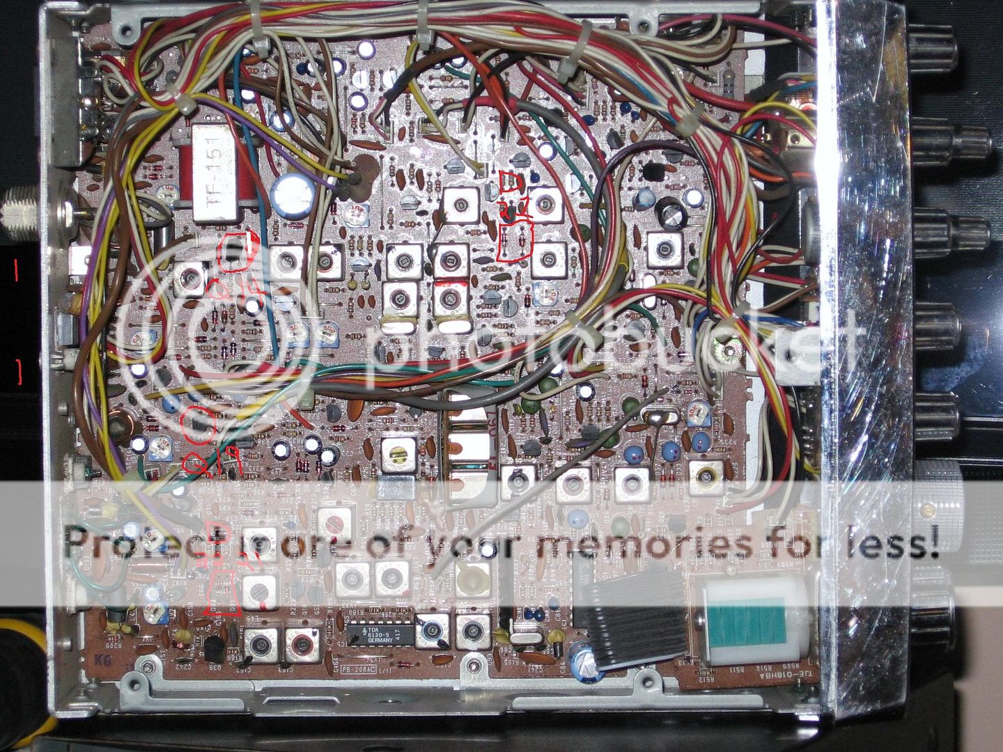
C95 is a 47uF electrolytic capacitor and it connects to pin 6 of IC3, the AN612 balanced modulator IC.
referring to your pic, start by looking at the big crystal filter. its that vertical PC board that has three crystals right next to eachother, each with a small ceramic disc cap on top of it. the plastic wrapping around it will say "FL-067" on it.
now look slightly in front of it, and slightly toward the mic connector and you will find IC 3. its a SIP (single inline package) which means it only has one row of leads on it.
once you find that, find pin 6 which is the second closest pin to the back of the radio. (the AN612 has 7 pins on it)
follow the trace from pin 6 and you should find the positive lead of C95 connected to it.
in your pic it looks like its probably under that bundle of wires, so cutting that cable tie and spreading the wires out should help you find it.
good luck and i hope that was your problem.
LC
the answer is yes, C95 does the same thing in all the dual conversion MB8719 chassis.
C95 is a 47uF electrolytic capacitor and it connects to pin 6 of IC3, the AN612 balanced modulator IC.
referring to your pic, start by looking at the big crystal filter. its that vertical PC board that has three crystals right next to eachother, each with a small ceramic disc cap on top of it. the plastic wrapping around it will say "FL-067" on it.
now look slightly in front of it, and slightly toward the mic connector and you will find IC 3. its a SIP (single inline package) which means it only has one row of leads on it.
once you find that, find pin 6 which is the second closest pin to the back of the radio. (the AN612 has 7 pins on it)
follow the trace from pin 6 and you should find the positive lead of C95 connected to it.
in your pic it looks like its probably under that bundle of wires, so cutting that cable tie and spreading the wires out should help you find it.
good luck and i hope that was your problem.
LC
i wrote up a tutorial on how to align a 148GTL which is very close to the same as your grants.
you can find it by searching this forum.
not sure what i titled it though, sorry.
this is from the factory service manual for the 2000GTL, but it should work with the 148gtl, the new grant, the new madison, and the tramD300 among others.if your radio has an MB8719 or MB8734 chip in it and a dual conversion receiver, then this alignment procedure should work for you.
for any other radio, you will have to find the specific service info for that radio. DO NOT USE THE NUMBERS IN THIS ALIGNMENT TO ALIGN OTHER RADIOS. YOU WILL SEVERELY DAMAGE THE RADIO!
when looking for sevice info, the internet is your best friend. you can often find the manuals on the auction site for a fair price.
if the radio is older than say, 10 years, then you should be able to find a SAMS PHOTOFACT for your radio. these were made by the Howard W. sams company. they are no longer made but you can find them around if you look. YOU MUST HAVE THE SERVICE INFO FOR THE RADIO YOU WISH TO ALIGN. DO NOT ATTEMPT THE ALIGNMENT WITHOUT THE SERVICE INFO AND THE TEST EQUIPMENT!
here we go:
1. input of frequency counter to TP13 (test point 13) IC1 pin 8.
radio on ch.19 am. clarifier in center pos. NB and ANL off.
check for 10.240mhz.
this means that you will hook the alligator clip rom the shield (-) or the freq. counter and clip it to PC ground. i like to use the tuning cans as they are all grounded. just clip right to the can, or if there is a wire soldered to it, clip to that. make sure the place you clip to is true ground. (connected to the big foil trace) and also make sure you dont use the metal case of the radio or "chassis ground" this is not the same as the PC board ground and will not work.
now take the probe from the freq. counter and touch the tip to pin 8 of IC 1. look at the freq. counter, it should read 10.240mhz. (if you get no reading and the radio seems to work correctly, then you have either hooked something up wrong or your freq. counter is set wrong or doesnt work.
2. input of RF voltmeter to TP10
radio on ch. 19am. clarifier centered.
adjust L21 for maximum RF out.
this means that you will clip the negative lead of your RF probe to where you had the freq. counter hooked to and the positive tip will go to TP10 (location found in service manual)
adjust the can SLOWLY for the maximum voltage. you will notice the volts rise to a point and then start to fall again, go back and forth until you find the peak point and leave the can set there.
3. input of DC voltmeter to TP9
radio set on ch. 40am
adjust L19 for 3.20 volts. check channel 1 for 2.45 volts.
this means set up the same way as before except dont use the RFprobe and set the can for 3.2 volts and leave it there.
4.input of RF probe to TP1.
radio set on ch.19am
adjust L20 for maximum voltage. (you may have to use the mV setting on the voltmeter for this one.
this is done the same way as in step 2.
5. input of freq. counter to TP1.
radio at ch.1 am
adjust L23 for 34.7650mhz + or - 20hz (try to get it exact)
6.input of freq.counter to TP1
radio at ch.1 USB
adjust L59 for 34.7665mhz.
7. input of freq. counter to TP1
radio at ch.1 LSB
adjust L22 for 34.7635mhz.
8. input of freq. counter to TP10
radio at ch.1am
check for .790mhz
9.input of freq. counter to TP3
radio at ch.19USB
adjust CT2 for 7.8015mhz
10. input of freq. counter to TP3
radio at ch.19LSB
adjust L30 for 7.7985mhz
11.input of freq. counter to TP14 (IC3 pin 7)
radio at ch.19 AM TRANSMIT (key mic with no modulation)
adjust L31 for 7.800mhz.
12. input of freq. counter to TP15 (FET 1 gate1)
radio at ch.19am
check for 7.345mhz.
13.input of freq counter to antenna input (so-239)
radio at ch.1 AM TRANSMIT
adjust VR5 for 26.965mhz.
thats it for the PLL section.
so here is the reciever alignment procedure.
for this you will be using your signal generator.
make sure you have a .01uf cap in series with the positive test lead.
to set the s-meter and the squelch; you will need a voltmeter that measures microvolts. i do not have one of these, and therefore, i cannot do an accurate adjustment on these two pots.
this is where the bench radio comes in handy.
the bench radio i have has an analog meter on it, and after performing a tune up on a radio, i will find a local with a steady carrier, and match the radio im tuning to the S-meter on the bench set.
same with the squelch. (you wont need to adjust this ever, unless someone has turned the pot by mistake, and then, its not the most critical adjustment on the radio)
for this radio, the squelch range is VR3, the AM s meter is VR1, and the SSB meter is VR2.
YES, i realize that this is not entirely accurate, and i do not claim it to be. if you want it completely perfect, you will have to take it to a tech with a higher quality signal generator.
you could buy a better one yourself, but i dont feel the need for it, and can always find something else to buy with that ammount of money.(more radios!)
here we go:
FOR ALL RECEIVER ADJUSTMENTS: RF GAIN MAX. CLARIFIER AT CENTER, SQUELCH AT MINIMUM, NB OFF, ANL OFF, TONE MAXIMUM CLOCKWISE.
1. output of signal generator to TP16 (TR15 emitter)
7.8mhz
radio at ch.19USB
adjust L14,12,10,9,8,7 in that order for maximum s meter reading.
so, set your sig gen at 7.8mhz, clip the negative lead to PC ground, and the positive lead to TP16.
adjust the output of the sig gen so that the S meter on the radio reads about S-3. (no more)
slowly turn the coils, starting at L14 and working down. you will notice that they cause the S meter to move up or down as they are turned. turn the coils SLOWLY until you find the peak reading. leave the coil in that position and move on to the next.
2.output of sig. gen. to TP15 (FET 1 gate 1)
455khz.
radio at ch.19AM
adjust L15,13,3 for max. s-meter reading.
same as last step.
3.output of sig. gen. to antenna input
27.185mhz.
radio at ch.19AM
adjust L6,5,4 for max. s-meter reading. readjust L7,8,9,10 for max. in that order.
i also adjust L1,and L2 at this time. these are the NB coils, and should be adjusted using an oscilloscope and very high quality signal generator.
at this point, its up to you whether or not to mess with them. if you are doing a tune up on a radio that you know the history of, then there is no need to adjust them. if, however, you happen to be working on a garage sale special that you want to get working; then adjust them for max. s-meter reading using the set up from the previous step. this is how i do it on my radios, and my ear cant tell the difference.
and finally, the transmitter alignment.
you should use a dummy load for these tests, if you dont, you will be causing malicious interference, and generally being a jerk. and your results wont be as accurate. dont do it!
hook up a wattmeter between the radio and the dummy load.
radio should be on ch.19
1.radio at ch.19 AM
key the mic, and say "aaahhhhh" in a steady natural voice tone. using a two tone generator here can be very helpful. there are numerous designs around on the net, and they are simple to build. i use one. do not tune the coils for max. deadkey, as this will weaken the modulation to a great extent, sometimes making the output power actually DECREASE when you are speaking. (downward modulation)
while speaking into the mic, adjust L47,48,46,45, and L38 in that order for max. peak (modulated) power. on one or more of these coils, you will notice that there is a waxy substance covering the opening. carefully pick this away, and then, right before you make your adjustment, put your soldering iron on the ferrite core for just two seconds. be careful not to melt the plastic threads on the edges. this will allow the core to turn easily. if you dont do this, you can break the core, and then you'll have to scrounge another one from a different radio which may or may not work as well. be careful, dont turn anything fast, and never force anything.
2.ch.19USB mike gain at minimum.
adjust VR4 for 0 watts. (no carrier)
3. ch.19USB mike gain at minimum.
insert DC ammeter at TP8. (driver bias)
this means that you need your DC volmeter set to milliamps on a scale that can read 200ma (milliamps).
this hook up is not the same as voltage testing! when you test for current, you hook the voltmeter in series with the lead under test.
so, pull the wire off of TP8, and clip the negative lead to the end. touch the positive lead to TP8. key the mic and adjust VR9 for 30ma.
reconnect the wire to TP8.
4. ch.19USB mike gain at minimum
pull wire off of TP7 and clip negative lead of voltmeter to it.
touch positive lead to TP7.
key the mic and adjust VR8 for 60ma.
reconnect the wire to TP7.
VR11 is your SSB power out. set it wherever you want it. if you are running an amp after the radio, you should set it for no more than 15 watts.
i set mine at 12 watts.
VR7 is the mod control in the 148 chassis. in the 2000 chassis its VR12.
i just set this at max and use the front panel mic again to adjust the modulation. (you wont have to run the mike gain all the way up anymore)
VR10 is the AM carrier power. this is where people blow up their radios. they say, "wow! how cool! the manufacturer put in an easy adjustment for more power out!" dont be fooled! most radios cant handle the increased wattage for very long when this is turned up.
if you are running an amp; set this control for 2-3 watts and NO MORE! otherwise you will sound very quiet coming out of your amp, and you may just smoke it!
if you are running barefoot, then set it for about 5 watts. this is safe, and no one can tell the difference between 5 and 8 watts anyway. your radio will last for a very long time if you keep this control under control. if you get the power bug, you will be buying transistors that are getting more expensive every day.
finally, adjust VR6 so that the S meter on the radio agrees with the wattmeter.
well, thats pretty much it, except for the 50 flaming posts ive got coming my way for condoning such cheap and dirty tricks.
make no bones about it. this is not as accurate as sending your radio to a good tech shop, but if you wanted to do that, you wouldnt have read this far would you!
good luck, and please feel free to point out any mistakes or bad advice that you see. all quesitons are good questions.
i will correct any mistakes tomorrow, gotta go for now.
LC
Last edited by a moderator:
B
BOOTY MONSTER
Guest
THANKS !
No, thanks to loosecannon. This was his information.
for the benefit of anyone using the alignment procedure posted here; it looks like i made a typo in step 10.
it should read 7.7985.
my apologies to anyone who used this in the past and had problems.
LC
it should read 7.7985.
my apologies to anyone who used this in the past and had problems.
LC
dxChat
- No one is chatting at the moment.
-
-
-
dxBot:boog351 has left the room.
-
@ BJ radionut:
June VHF
The American Radio Relay League (ARRL) is the national association for amateur radio, connecting hams around the U.S. with news, information and resources.www.arrl.org
-