• You can now help support WorldwideDX when you shop on Amazon at no additional cost to you! Simply follow this Shop on Amazon link first and a portion of any purchase is sent to WorldwideDX to help with site costs.

Old uniden Grant PC409ac board

I bought this radio a couple months back from @H1driver and it is dang near mint condition and all virgin inside. Pc-409AC pcb and I'm guessing this guy goes back a few years but not sure to the exact time.

Can anyone give me a window of when these were produced?

I ask because I'm thinking this winter would be a good time for a recap with a kit from Klondike Mike. 20220702_151923.jpg
 

Attachments

  • 20220702_151251.jpg
    20220702_151251.jpg
    691.4 KB · Views: 22
  • 20220702_151238.jpg
    20220702_151238.jpg
    785.7 KB · Views: 23
  • 20220702_151215.jpg
    20220702_151215.jpg
    1.2 MB · Views: 25
  • 20220702_151130.jpg
    20220702_151130.jpg
    1.3 MB · Views: 21
  • 20220702_151120.jpg
    20220702_151120.jpg
    1.4 MB · Views: 23
  • 20220702_151126.jpg
    20220702_151126.jpg
    1.4 MB · Views: 21
MB8719 PLL chip marks this as a second generation radio. First generation were uPD858. So probably the earliest this would have been made would be about 1978.
 
  • Like
Reactions: Eldorado828
The "8911" date code on the 8719 PLL indicates the 11th week of 1989. Of course, that's only when the chip was made. If it is in fact the factory-original part, the radio was probably built later that year or the next, 1990. If it says "Taiwan" it would be among the last CB radios built in that factory before they moved production to the Philippines.

73
 
you are very welcome.

congrats on the new radios.
be nice to them. the MB8719 PLL chip that is in those radios is VERY sought after and very hard to find. can you say expensive?!

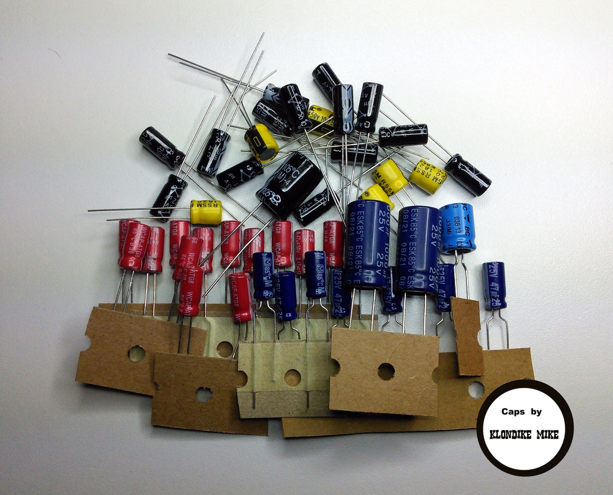
i am a huge proponent of replacing all the electrolytics in these old radios, and you will find that they work AWESOME once you do it.
make sure you use 16 volt or higher caps. the ones rated at 10 volts never should have been used.

remember that the radio might need an alignment after you do this, as the values of the new caps will be a bit different than the old ones.

i wrote up a tutorial on how to align a 148GTL which is very close to the same as your grants.
you can find it by searching this forum.
not sure what i titled it though, sorry.

here are a few upgrades you should do when you are replacing all the caps.
these are not "peak and tweak" mods that mess up the radio, they are parts upgrades that make it work better.

replace Q41 with a 2N6487 or an NTE152.
this is the AM power reg. and the stock ones are underrated for what they do.

replace the main filter cap (i think its C172) with a 2200uF or 3300uF 25 volt cap.
this will give the radio some better headroom during modulation peaks.

replace C18 with a 680-1000uF cap.
this filters the mic line better and keeps the radio from squealing if you turn up the audio.

you can speed up the AMC attack time by replacing C109 with a 3.3uF cap.

replace C181 with a 1000uF cap. better filtering for the power supply.

the 2SC2999 receive mod works great in this chassis, and i highly recommend it.
you can buy the kits on ebay pretty cheap, as the 2999 can be hard to find on your own.

the diodes used are shottky barrier diodes. 1n6263 or NTE583.
replace Q14 with the 2SC2999 and replace D1, D2, D21, and D22 with the shottky diodes.
they are the AM detector and the noise blanker diodes.


there are many more mods for this chassis, and ive probably tried them all.
most of the modulation mods are actually worse than the radio is stock.

after trying all the mods, i now run my base station stock with a D104 silver eagle and it sounds great.

in the mobile i will remove R131 which disables the AM limiter but leaves the SSB circuits alone.
never remove or modify TR24 as it will cause SSB distortion.
changing R124 and 126 like all the google mods say will just make the radio want to squeal and make the audio sound muffled.

good luck with those radios and feel free to PM me if you have specific questions.
can you tell i love these radios? LOL
LC

oh, and i drink Sierra Nevada IPA. LOL
Hey loose cannon my name is wildcat and I have a uniden grant pc 409 and I have the sams # 221 and I'm having a problem..this thing is different than theres I replaced the caps and there is no pa or transmit the red light that changes over when you push the ptt doesn't change over there was a loud humming thru out the radio to but I got that stopped man I really need some help thanks .
 
Any time some function of a radio quits, it's a good idea to check the power supply section that powers the missing function.

That radio has a chip that provides a regulated 8 Volts DC to the radios' critical circuits. It's the MB3756 marked IC4 on the schematic. It's bolted to the aluminum chassis' side rail near the front. The pin closest to the front is pin 8. The one at the rearmost end is pin 1. Pin 1 should show a steady 8 Volts DC all the time, transmit and receive.

Pin 6 should have 8 Volts DC only while receiving and go to zero while transmitting. Pin 8 should have 8 Volts in transmit mode, zero while receiving.

Unless all 3 of those are accounted for, the radio will be crippled.

73
 
  • Like
Reactions: NZ8N
And if those voltages aren't as Nomadradio states and you have 13 volts where there should be 8 volts......then you may also kiss your PLL (8719) goodbye.....Don't ask me how I know.
 
Hey loose cannon my name is wildcat and I have a uniden grant pc 409 and I have the sams # 221 and I'm having a problem..this thing is different than theres I replaced the caps and there is no pa or transmit the red light that changes over when you push the ptt doesn't change over there was a loud humming thru out the radio to but I got that stopped man I really need some help thanks .

Tristan,

nomad has good advice for you.

you might have one of your new caps installed backwards, or you might have inadvertently created a solder bridge on the solder side of the board.

get a bright light and a magnifying glass and look over everything very carefully.

let us know if you find anything and we'll go from there.
LC
 
Here goes a little resuscitation to this thread. As shown above, a couple of years ago I acquired one of these and it's time to put it on the bench for a recap so it can get used in the fall.

I don't have it front of me now but looking at the photos I see there's no dead key VR on the pcb like on the 148's. I'd like to get the carrier down to pair it with a Texas star 399.

Is it possible to add the vr to this pc-409ac board to get the adjustable dk?
 
The schematic is here: https://cbtricks.org/radios/president/grant/graphics/president_grant_pc409_sch.pdf

Unless the host's bandwidth limit was reached that hour.

Says VR10 sets the AM carrier. VR10 will turn it down only so far. The lower limit is set by R196, a 4.7k resistor connected to one end of VR10 and ground. A short across R196 allows you to turn the carrier lower.

Just one caveat. Too much audio can burn out VR10 when it's turned too low. Cutting the trace at the wiper (center) lug of VR10 is step 1. A 1N4148 diode gets its anode (no band) end to the now-isolated wiper lead of VR10. The cathode (banded end) goes to the other side of the cut trace. A 10k 1/4w resistor goes from the cathode of the new diode to ground.

This will permit a low carrier setting and protect VR10 from excessive audio voltages.

73
Very well explained, thank you Nomad. I'm hoping to start this project once I order and receive the cap kit from @Klondike Mike.

I'll report back when I'm at that point.

Thank you again
 
... once I order and receive the cap kit from @Klondike Mike.

Yup. Available here;

https://klondikemikescapkits.com/pr...ic-capacitor-kit?_pos=1&_psq=409&_ss=e&_v=1.0

grant409pile2c_1024x1024@2x.jpg
 

dxChat
Help Users
  • No one is chatting at the moment.
  • @ Wildcat27:
    Hello I have a old school 2950 receives great on all modes and transmits great on AM but no transmit on SSB. Does anyone have any idea?
  • @ ButtFuzz:
    Good evening from Sunny Salem! What’s shaking?
  • dxBot:
    63Sprint has left the room.