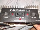
I recently aquired a Palomar 225 linear amp (has black label & 2 MRF 455 pwr transistors, not blue label). It has a burnt (so badly I can't read the value) 2 or 3 watt resistor right next to the transmitter input. Does anyone know of a schematic for the amp? Or what other components maybe affected by the resistor burning? Thanks!

You are using an out of date browser. It may not display this or other websites correctly.
You should upgrade or use an alternative browser.
You should upgrade or use an alternative browser.
-
You can now help support WorldwideDX when you shop on Amazon at no additional cost to you! Simply follow this Shop on Amazon link first and a portion of any purchase is sent to WorldwideDX to help with site costs.
-
A Winner has been chosen for the 2026 July 4th Retevis RA89R Giveaway! Click Here to see who won!
Palomar 225 w/2 MRF 455's
- Thread starter fastfreddie1269
- Start date
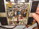
That resistor is in series with the radio's drive power to the transistors. A pair of MRF455s only needs about ten or twelve watts peak to smack them fairly hard. Even a wimpy AM CB does half-again more or twice that. You'll be hard pressed to find a radio that small. The resistor serves two purposes. FIrst, to bleed off some of the radio's excess drive power, and to hold the amplifier's input impedance somewhere close to 50 ohms. The input of an amplifier should fool the radio into thinking that it's connected to an antenna with a low SWR. The resistor increases the amplifier's input impedance, hopefully to pin it near that 50-ohm mark. That resistor took it on the chin when somebody used a radio with two final transistors, or some other excessively-large output circuit.
That amplifier sure looks like the ones a friend was selling back around 96 or 97 when yours was probably made. The transistors are marked with a 1996 production date. The amplifier was probably built soon after that. I'll look to see if any diagrams of those amplifiers can be found next time I get to our shop.
73

Hi, I was asking about a schematic for a "black label" Palomar 225 a while back and was wondering if anybody was able to find it? I have one for blue label 225 & they def aren't the same! ThanksThat resistor is in series with the radio's drive power to the transistors. A pair of MRF455s only needs about ten or twelve watts peak to smack them fairly hard. Even a wimpy AM CB does half-again more or twice that. You'll be hard pressed to find a radio that small. The resistor serves two purposes. FIrst, to bleed off some of the radio's excess drive power, and to hold the amplifier's input impedance somewhere close to 50 ohms. The input of an amplifier should fool the radio into thinking that it's connected to an antenna with a low SWR. The resistor increases the amplifier's input impedance, hopefully to pin it near that 50-ohm mark. That resistor took it on the chin when somebody used a radio with two final transistors, or some other excessively-large output circuit.
That amplifier sure looks like the ones a friend was selling back around 96 or 97 when yours was probably made. The transistors are marked with a 1996 production date. The amplifier was probably built soon after that. I'll look to see if any diagrams of those amplifiers can be found next time I get to our shop.
73
Hey, I just dug out this Dynamo 175 amp that I was playing with
over a year ago, adjusting the bias, by-passing RX pre-amp,
correcting the RF input circuit. I got it working good.
I always wanted the proper schematic.
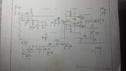
and I just found the schematic this morning! maybe?
"AUTOMATIC SIDE BAND" "CLASS AB1"
Palomar 225
as mentioned, I have the Dynamo 175
also known as a White Tornado 225, Shooting Star 225

over a year ago, adjusting the bias, by-passing RX pre-amp,
correcting the RF input circuit. I got it working good.
I always wanted the proper schematic.
and I just found the schematic this morning! maybe?
"AUTOMATIC SIDE BAND" "CLASS AB1"
Palomar 225
as mentioned, I have the Dynamo 175
also known as a White Tornado 225, Shooting Star 225
Attachments
Here is my older post. it looks like resistor R14 was changed to 100 ohms.
and I disconnected that screwball input circuit, and just have one
resistor there, and I feed this with a China made Cobra 148.
The extra 400 W power amp is blown up.
(aren't they all? this N4 amp set-up looks like a potential disaster!)
So bypassed this N4 amp, and now a bare 2970 here. so have the carrier down
to two watts or less and barely turn up the mic gain. have good AM
out of this amp, maybe 30 watts carrier.
but maybe I can come up with a proper attenuator circuit wired up
to the front panel switch, for a 4 and/or 8 watt radio input.
and I disconnected that screwball input circuit, and just have one
resistor there, and I feed this with a China made Cobra 148.
oh yes, yes, on the 2970. I have a broken 2970N4 here.- do not run a 2970 with any of those amplifiers. Way way too much radio.
The extra 400 W power amp is blown up.
(aren't they all? this N4 amp set-up looks like a potential disaster!)
So bypassed this N4 amp, and now a bare 2970 here. so have the carrier down
to two watts or less and barely turn up the mic gain. have good AM
out of this amp, maybe 30 watts carrier.
but maybe I can come up with a proper attenuator circuit wired up
to the front panel switch, for a 4 and/or 8 watt radio input.
took a look over that schematic diagram.
but the bias circuit on this diagram is messed up.
at relay RLY1 - 14,15,16 just a drawing mistake. ?
and that feedback through the 27pF capacitor from the
amplifier output. hmmm!
so will pull the board out, and do some continuity tests.
so the PALOMAR ELITE 250 is the same circuit as I remember. ?
I had a few of them here from a guy in town. I gave them all back
to him. I was too busy at the time.
so fastfreddie1269 we will get you rolling here soon.
dxChat
- No one is chatting at the moment.