• You can now help support WorldwideDX when you shop on Amazon at no additional cost to you! Simply follow this Shop on Amazon link first and a portion of any purchase is sent to WorldwideDX to help with site costs.

Pll02A crystal info needed.

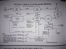
Those 20.105 crystals may actually work. The 10.0525 is quadrupled to 40.21, so the 20.105 should ring the 40.21 tuned transformer just the same.
The 10.0525 is doubled in this 02A to 20.105 then fed to the mixer. I thought of the 20mhz xtal but I would likely have to make my own oscillator.1788453682275455385023888047066.jpg
 
  • Like
Reactions: brandon7861
Thanks for sharing that. I assumed (4*10.0525)-37.66=2.55, but I hadn't considered it mixed twice to get the PLL input like that 37.66-20.105=17.555 and 20.105-17.555=2.55. My brain was searching for the simplest solution.

Would be interesting to know if the 20.105MHz crystal would work in that oscillator.
 
Thanks for sharing that. I assumed (4*10.0525)-37.66=2.55, but I hadn't considered it mixed twice to get the PLL input like that 37.66-20.105=17.555 and 20.105-17.555=2.55. My brain was searching for the simplest solution.

Would be interesting to know if the 20.105MHz crystal would work in that oscillator.
I bet it could, would need an oscillator board with varactor tuning for the clarifier and ssb offset though.

Edit, I think it can be made to work in the existing circuit with a few changes, so no oscillator board required.
 
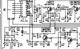
I thought that oscillator already had the varactor control on it. I am looking at the 79-892 schematic from cbtricks and it looks like the varactor is brought into circuit at the emitter via C18.
1788455662050.png
I imagine some of those caps would need to get smaller around Q3 and on the trimmer side of the inductor but it might be possible. IDK
 
I thought that oscillator already had the varactor control on it. I am looking at the 79-892 schematic from cbtricks and it looks like the varactor is brought into circuit at the emitter via C18.
View attachment 77704
I imagine some of those caps would need to get smaller around Q3 and on the trimmer side of the inductor but it might be possible. IDK
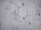
It does, I was talking about making my own oscillator and needing varactor diode, but I think a xtal swap and a few circuit changes alone should work. I'm using a Sam's for the schematic...
1788458199114887140959248384564.jpg
 
  • Like
Reactions: brandon7861
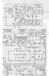
Here's a pic of the export band mods, it wouldn't take much to adapt with a bit of veroboard. 20Mhz for the win :)

Looking at the circuit I believe it still uses the doubler, the crystal has a diode in line so maybe that halves the frequency anyway.

Cybernet-xtals.jpg
 
  • Like
Reactions: Cable Guy
Here's a pic of the export band mods, it wouldn't take much to adapt with a bit of veroboard. 20Mhz for the win :)

Looking at the circuit I believe it still uses the doubler, the crystal has a diode in line so maybe that halves the frequency anyway.

View attachment 77706
Diodes are signal switching. The band switch forward biases one at a time selecting which crystal is connected to the oscillator. The diodes are not halving anything. The doubler is just a tank circuit tuned to 20MHz so you can put 10MHz or 20MHz into it and it will do its job the same, output 20MHz.
 
  • Like
Reactions: Cable Guy

dxChat
Help Users
  • No one is chatting at the moment.