So I've been thinking about gain, and as some of you may know I operate exclusively mobile, for those that didn't know, now you do 
I also only use the amateur bands for SSB, although I still use the UK CB allocation and mode (FM), but no where near as much as I do amateur frequencies.
So that's the bit about me and what I do, now back to the subject matter, a portable antenna with gain. I wanted to build an antenna I could take to the beach / seaside and benefit from vertical polarisation and enhanced gain. Some of the ideas were phased verticals, I have a couple of friends who use portable phased verticals, and whilst only 1/4WL long (relatively short), they require a good set of radials and a phasing system. neither of this are difficult to make, but they do add to the complexity of a system that will be used in public and put up and taken down in the same session.
So this got me thinking, what about a Yagi antenna, not a horizontal, but a vertical Yagi, one that will be ground mounted and benefit from operating over, or near, salt water. The benefit of ground mounting is no need for a tall tower, simple construction, and if fed at the base of the driven element, no complex coax support or interaction from a drooping coax. Ok so how do we make it a driven element with a base feed? Ok so it's not truly fed at the base of the element, it uses the same principle of the coax dipole, the coax comes in at the base, but relies on common mode current to create the lower section of the antenna.
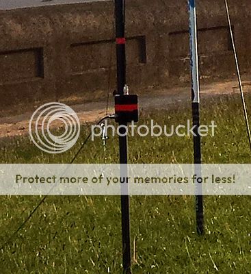
So I've overcome the feed arrangement, how do I stop the common mode current at the base, well I could use a coil of coax, but efficiency wise that is the worst choice, not a bad choice, but could be better. If I follow Steve Hunt's (G3TXQ) chart I can see that an FT240-61 torroid, with 8 turns of RG 58, will give me excellent choking impedance at my desired frequency (28.5MHz). If I enclose the torroid in a small project box I can also add SO239 connectors to the box for the antenna element and the feedline to connect to. This tidies things up again, simple and clutter free.
That's common mode dealt with, now how do I deal with the low feedpoint impedance, around 24ohm, I had to think about this one for a while, but hit on an idea, what does a 1/2WL element have at either end? very high impedance, and at the centre I know it has a low impedance, somewhere along either the upper or lower half of the driven element will be a point that matches to my coax impedance, all I have to do is find it. Well I've been using MANNA-GAL to model the antenna, so I just adjusted the feedpoint on the driven element and hey presto, 50ohm. So the antenna has an off centre feedpoint, and if I make the lower portion of the antenna shorter, and the upper portion longer, I also save on coax usage (ok so I'm tight with my money ).
).
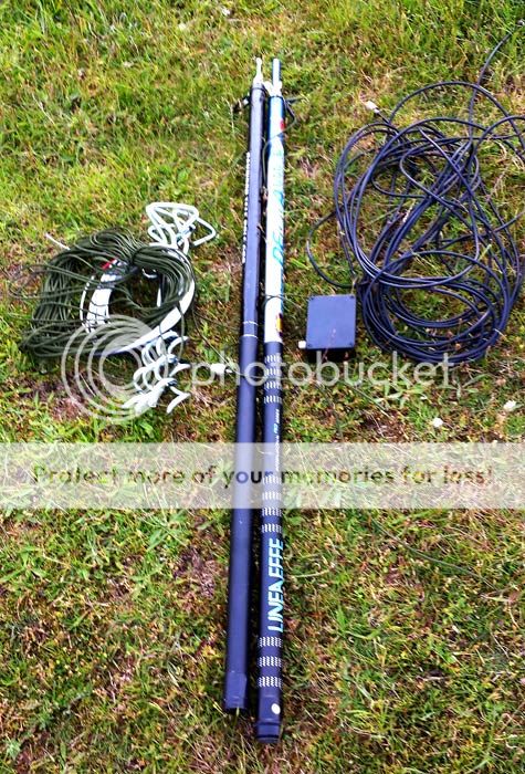
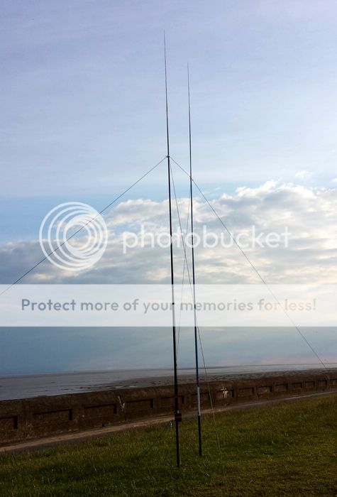
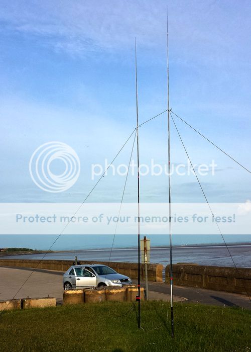
So hopefully I'm building an image of what the antenna is, to use in the field it will require support, a couple of 6m fibreglass telescopic fishing poles comes to the rescue there, with connecting paracord between them I can maintain the 1m separation between driven and director elements, I also use four lengths of paracord to keep the poles upright, two on the driven pole and two on the director, with the connecting rope supporting each other.
Ok no pictures yet, I had made a video earlier on and realised I'd done it in portrait mode rather than landscape, and that just won't do, so I'll make another video tomorrow along with some pictures for your delectation.
What I can show is a model of the antenna over sea water, you can see the front to back, the elevation angle and gain:
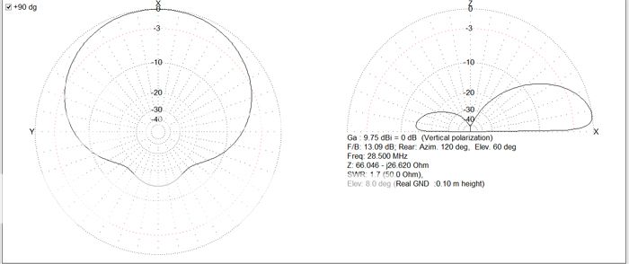
Ignore if you will for a moment the higher than 50ohm feedpoint in the model, I made some changes to element diameter and feedpoint which changed things a little when I took the snapshot. I will also give the specific dimensions when the antenna is tuned and tested along with the final modeling.
Hopefully it's given you some ideas to try of your own, my intention is to make one for 20m (my favourite DX band of choice), but wanted to make a smaller version first, I can also make different elements covering other bands, once the 20m version is complete, as I already have the 10m long support poles and I'll be making another, more wideband, choke. The simplicity of using SO239/PL259 connectors as the antenna base
What you can also see in the model is the very wide beamwidth, this is perfect for my usual location that has a great take off to N, W, S, this covers Australia and Pacific long path, New Zealand short and long path, USA East, Mid and West short path, Caribbean and South/Central America short path.
Does it work? Well it isn't properly tested yet, however I used it on the UK CB band the other night and can confirm F/B was around 10-12dB with local stations, this was with the antenna resting against my wall and moving the director element in front, and then behind, the driven element, up to 2 S points reported by local CBers, I can't wait for Monday when I'll get a chance to use it by the beach :w00t:
I also only use the amateur bands for SSB, although I still use the UK CB allocation and mode (FM), but no where near as much as I do amateur frequencies.
So that's the bit about me and what I do, now back to the subject matter, a portable antenna with gain. I wanted to build an antenna I could take to the beach / seaside and benefit from vertical polarisation and enhanced gain. Some of the ideas were phased verticals, I have a couple of friends who use portable phased verticals, and whilst only 1/4WL long (relatively short), they require a good set of radials and a phasing system. neither of this are difficult to make, but they do add to the complexity of a system that will be used in public and put up and taken down in the same session.
So this got me thinking, what about a Yagi antenna, not a horizontal, but a vertical Yagi, one that will be ground mounted and benefit from operating over, or near, salt water. The benefit of ground mounting is no need for a tall tower, simple construction, and if fed at the base of the driven element, no complex coax support or interaction from a drooping coax. Ok so how do we make it a driven element with a base feed? Ok so it's not truly fed at the base of the element, it uses the same principle of the coax dipole, the coax comes in at the base, but relies on common mode current to create the lower section of the antenna.
So I've overcome the feed arrangement, how do I stop the common mode current at the base, well I could use a coil of coax, but efficiency wise that is the worst choice, not a bad choice, but could be better. If I follow Steve Hunt's (G3TXQ) chart I can see that an FT240-61 torroid, with 8 turns of RG 58, will give me excellent choking impedance at my desired frequency (28.5MHz). If I enclose the torroid in a small project box I can also add SO239 connectors to the box for the antenna element and the feedline to connect to. This tidies things up again, simple and clutter free.
That's common mode dealt with, now how do I deal with the low feedpoint impedance, around 24ohm, I had to think about this one for a while, but hit on an idea, what does a 1/2WL element have at either end? very high impedance, and at the centre I know it has a low impedance, somewhere along either the upper or lower half of the driven element will be a point that matches to my coax impedance, all I have to do is find it. Well I've been using MANNA-GAL to model the antenna, so I just adjusted the feedpoint on the driven element and hey presto, 50ohm. So the antenna has an off centre feedpoint, and if I make the lower portion of the antenna shorter, and the upper portion longer, I also save on coax usage (ok so I'm tight with my money
).So hopefully I'm building an image of what the antenna is, to use in the field it will require support, a couple of 6m fibreglass telescopic fishing poles comes to the rescue there, with connecting paracord between them I can maintain the 1m separation between driven and director elements, I also use four lengths of paracord to keep the poles upright, two on the driven pole and two on the director, with the connecting rope supporting each other.
Ok no pictures yet, I had made a video earlier on and realised I'd done it in portrait mode rather than landscape, and that just won't do, so I'll make another video tomorrow along with some pictures for your delectation.
What I can show is a model of the antenna over sea water, you can see the front to back, the elevation angle and gain:
Ignore if you will for a moment the higher than 50ohm feedpoint in the model, I made some changes to element diameter and feedpoint which changed things a little when I took the snapshot. I will also give the specific dimensions when the antenna is tuned and tested along with the final modeling.
Hopefully it's given you some ideas to try of your own, my intention is to make one for 20m (my favourite DX band of choice), but wanted to make a smaller version first, I can also make different elements covering other bands, once the 20m version is complete, as I already have the 10m long support poles and I'll be making another, more wideband, choke. The simplicity of using SO239/PL259 connectors as the antenna base
What you can also see in the model is the very wide beamwidth, this is perfect for my usual location that has a great take off to N, W, S, this covers Australia and Pacific long path, New Zealand short and long path, USA East, Mid and West short path, Caribbean and South/Central America short path.
Does it work? Well it isn't properly tested yet, however I used it on the UK CB band the other night and can confirm F/B was around 10-12dB with local stations, this was with the antenna resting against my wall and moving the director element in front, and then behind, the driven element, up to 2 S points reported by local CBers, I can't wait for Monday when I'll get a chance to use it by the beach :w00t: