
You are using an out of date browser. It may not display this or other websites correctly.
You should upgrade or use an alternative browser.
You should upgrade or use an alternative browser.
-
You can now help support WorldwideDX when you shop on Amazon at no additional cost to you! Simply follow this Shop on Amazon link first and a portion of any purchase is sent to WorldwideDX to help with site costs.
-
A Winner has been chosen for the 2026 July 4th Retevis RA89R Giveaway! Click Here to see who won!
power output question about the sd1446
- Thread starter cjruger
- Start date
From the pictures of this amp we can clearly see something is missing. No negative feedback is present and would be the number one cause of his symptoms. Not bad for a "crap shoot" based on limited info.
Man pictures right from the start would have cut to the chase for sure. Now he must decide if it's worth fixing or sell it as is and buy a nice AB amplifier.


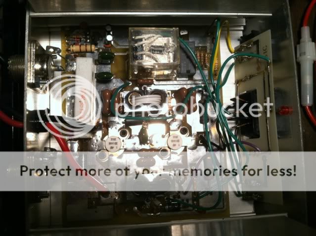
This is the negative feedback circuit that Shockwave is referring to. I added the resistors and caps since the amp did not have them installed. Note the 100 ohm resistors and the .01uf disc caps from the Base to Collector of each transistor.
I also moved the diode for the bias from above the board (why the hell they put the diode there is lost on me) to below the board so it touches the heat sink so it will thermally track. I also added a dot of thermal heat sink compound where the diode touches the heat sink for better thermal transfer. You can see that there's 2 empty "pads" to the front and right of the front transistor where there was a diode soldered into.. it's underneath that same spot now.
Hope this helps clarify the negative feedback circuit, and what it will generally look like if installed in an amp.

~Cheers~
I also moved the diode for the bias from above the board (why the hell they put the diode there is lost on me) to below the board so it touches the heat sink so it will thermally track. I also added a dot of thermal heat sink compound where the diode touches the heat sink for better thermal transfer. You can see that there's 2 empty "pads" to the front and right of the front transistor where there was a diode soldered into.. it's underneath that same spot now.
Hope this helps clarify the negative feedback circuit, and what it will generally look like if installed in an amp.
~Cheers~

So what does this negative feedback add to the amp? Can this amp harm my radio in any way?
In order for the amp to damage your radio, it would probably have to get a little worse than it is now. While the amp does oscillate when keyed, it does not self oscillate and keep itself keyed once you let got of the mic. This is a possibility and if it self oscillates when your TX is not keyed, it could wipe out the front end of the radio.
When an amplifier self oscillates there is enough positive RF feedback to its input to keep the cycle going even after you remove the external RF drive from the radio. Self oscillations will hold the keying relay closed and therefore connect this high level RF feedback right to the receiver. Depending on the amount of RF, it may do nothing or do lots of damage.
so I am reviving this thread a year later. I have pulled this off the shelf and temporarly set it up in the mobile. Seems to work good but as this thread discussed, there are issues with the amp. Any chance someone could take my pics and sketchin where I could add the neg. feedback components?. I would like to try it but cant figure out what to put where from the posts?
The picture that 13 posted shows the two resistors and the two caps you need to add for negative feedback, compare your amp to them.
There is also a another problem some of these black face clone, vertical transformer amps had, they often had all the parts for bias, but it was grounded out preventing it from working properly.
Many were built with the bias grounded out under the board.
As stupid as this sounds, it was done because the guys building these things were clueless, they ran into these stability problems and this is how they dealt with it.
Gain actually goes up with proper bias, by defeating the bias, running the amp in class c, they reduced gain to "try" to prevent the stability problem.
Many of the black face 4x1446 amps with vertical transformers suffer the same problem.
Many were built without neg feedback, poor input/output tuning and running in class c.
As I think has already been posted, adding neg feedback, reworking the input/output tuning, and checking to see if there is indeed bias voltage present at the transistors will go a long way towards making a decent amp out of these things.
Exit 13, do you still have this amp?
I would be interested to know what you find if you manually key the amp with no drive and check the voltage on the base of the transistors.
73
Jeff
Having a similar issue with a Palomar 250 2 1446 transistors amp. SWR are 1.1 without amp. When amp is on they jump up to a 2.5 when you modulate they go down to around 1.3. Trying to get some help to get this resolved. I'm using a uniden washington radio and have tried a 1 to 3 watt dead key they are better with higher dead key. I was thinking this negative feedback modification may help. I'm not sure whether to just add the 100ohm resistors and .01 ceramic cap in series across base to collector for both transistors or would this amp need another modification to correct this issue.. Any advice or ideas would be sincerely appreciated... Thanks for your help
Attachments

usually it's not the amp that needs a modification, it's the installation.
This negative feedback circuit, while a good mod for any amp, is probably not going to solve your problem.
you need to do a few tests and report your findings back here in order for us to really help.
do not pay any attention to your SWR when you are modulating.
it means nothing.
always turn your mic gain all the way down when checking SWR.
first thing to do is confirm that you are doing your testing the right way.
You may know this stuff, but it doesnt hurt to check to see if you have it right.
the set up should be, radio to SWR meter to antenna. no amp in line. CB channel 1.
key mic, calibrate SWR meter, switch to SWR setting on meter, read and note SWR reading.
now repeat this same exact procedure on channel 40, being sure to re-calibrate the SWR meter. note the SWR reading, and compare it to your reading on channel 1.
now repeat the same test on channel 20, once again making sure to re-calibrate the SWR meter. note the SWR reading. it should be lower than your numbers on 1 and 40.
this is your SWR curve, and a good one will be below 2:1 on 1 and 40, and below 1.5 on channel 20. yes, you can get away with an SWR higher than this, but when you run an amp, it can cause some problems.
ok, if this all went well, then you can put the amp in line.
if your tests did not come out about the way i described them, stop here for now and post your results in this thread.
moving on, put the amp in line, but put the SWR meter BEFORE the amp.
that would mean that the chain goes: radio to SWR meter, to amp, to antenna. (
this will tell us the input match to your amplifier and alleviate one possible problem area.
now do your tests again the exact same way, (amplifier on) on the same channels, and note each reading.
This SWR reading going into the amp should be below 2:1 for sure, and preferably below 1.5:1.
if your readings are 2 or more at this point, stop, and post your findings here.
if all went well, we can move on to the third phase of testing, and put the SWR meter after the amp.
so the chain would be radio to amp to SWR meter to antenna.
once again, do the same tests the same way, (amplifier on) re-calibrating at every channel you test on.
note the SWR readings and post them here.
if after all this, you find that the match without the amp is good, and the match into the amp is good, and only the SWR out of the amp is bad, then we have a few possibilities.
one is that the amp is being driven too hard which will cause the amplifier transistors to go into oscillation. this causes lots of harmonics to be emitted and your antenna won't like that. (2 transistor amps usually only like a watt or maybe two watts deadkey into them)
another possibility is that one of the transistors has gone bad, causing a mismatch on the output. if you notice one transistor gets hot and the other stays cool, this is probably the case. do not try to feel the heat on the transistors while you are keyed up because you might just be feeling RF and not residual heat. feel them right after you have had the amp keyed for around 10 seconds.
the other main possibility is that the output of the amp is dirty and spewing out harmonics regardless of drive level.
the way to test this is to put a low pass filter after the amp, and then put the SWR meter after that, and see if the SWR reading goes down.
the chain here would be: radio to amp to low pass filter to SWR meter to antenna.
ok, this should give you some things to try. get as much information together and post it all here.
the more detailed you are with your descriptions, the better help we can lend.
good luck.
LC
Last edited:
dxChat
- No one is chatting at the moment.
