• You can now help support WorldwideDX when you shop on Amazon at no additional cost to you! Simply follow this Shop on Amazon link first and a portion of any purchase is sent to WorldwideDX to help with site costs.

Question on an upcoming refurbishment....

guitar_199

Sr. Member
Mar 8, 2011
911
1,180
153
Deer Park, TX
A long time ago I found a Tram D201A on the local Facebook marketplace for stupid low money. Initial tests showed that is works.... "kind of"!!!! But I wound up just setting it to the side to hold it for a better time. I keep looking at it.... and started thinking.... "why not now?".

With that, I want to ask for some advice and discussion from the "community".

First off I have a copy of the document that has been floating around for years that recommends various pieces and parts (mostly resistors) on these D201A's. Then... most advice says to just "wholesale swap" electrolytic capacitors. What I do see from time to time... is WARS that start over the concept of "replacing parts across the board" versus "figuring out what is wrong and fixing it" in one like this. I know what my own thoughts are and they lean towards.... replace the old parts FIRST and then see what is LEFT to fix.

With that said, I'd still like to survey the group and see what others think... especially when this is such a "well thought of" radio... and it would be my first tube radio. I am absolutely confident in my ability to handle the work and have even worked with high voltages/tube in amplifiers before.

I mean, I look at this thing... there are multiple boards. I can focus on one at a time replacing caps and the other piece parts so as to "not get lost". It is my thinking that replacing these parts may indeed fix some of the shortcomings! (my memory is a little short on what I found in detail... but for the most part it did work. Piping RF into it... AM RCV worked... as near as I tested.... I got responses on SSB RCV ... it was better in LSB... and a few channels did not want to RCV in USB but I did not record details. It did wiggle my power meter on XMT in AM and LSB... but I do NOT think that it did XMT in USB).

But I think that the time has come and just wanted to know what others thought... and why they think it!!!!!!!

I would appreciate any responses/discussions!
(AND.... I can put up with a good 'jack slapping' too!!!!!!! :) )

Thanks a bunch,
Bob
 

Put me in the "swap first, ask questions later" camp. I've found electrolytics that appear to be OK from just looking at them that showed corrosion on the leads from leaking when removed. Less of an issue with the D201 and its axial caps, of course.

I also like to swap out known troublemaker components before throwing volts at them. Also, anything that's had glue on the leads gets yanked and at least cleaned off if not swapped out.

The key is to do all this carefully and methodically. I mark everything I intend to swap out with a sharpie so that I have a physical reference to how the part was mounted in the radio originally. It helps when I get interrupted and come back to a part that I don't remember which way it was facing when I yanked it out. It also helps when the markings for polarity on the board are wrong. Resistors don't usually get marked since orientation doesn't matter.

If I have to take a large number of components out in an area to clean up a mess underneath them or to facilitate removing a hard to reach component I'll take pictures as well and try to lay everything out in some semblance of where it was inside the radio in relation to the other parts around it. If a part is big enough I may even write it's "name" on it.

The big problem with swapping first is that you might induce a problem if you screw up somewhere. I've done that enough to know. Occasionally you'll get a component that's failed right out of the box. All you can do when either of these things happens is to troubleshoot like any other problem and do not assume that just because it's new it must be good and/or that you installed it correctly.

Finally I want wish you good luck on this endeavor. I've bought one D201 and it was shipped with a loose transformer inside after apparently sitting out in the weather for a few years. Sometimes you just can't save 'em.
 
There is a name for the process of replacing only the electrolytics that are causing trouble today. It's called "Electronic Whack-A-Mole".

You wouldn't question the wisdom of replacing every rubber hose in a 1975 car's engine. The point of failure in aluminum electrolytic capacitors is typically the rubber plug that seals in the electrolyte. Capacitor won't work without that stuff. Rubber plug on the capacitor gets old, stiff and shrinks every so slightly. Breaks the seal on the aluminum body and stuff evaporates.

Not a question of "if" but of "when". Exposure to heat accelerates this process. A new-old-stock part kept in that proverbial cool, dry place will frequently check okay. But exposure to the heat of operating causes that part to "remember" how old it is before too long. And a part with thousands of operating hours on it is likely to go bad after this long.

If you do this for hire, covering all the bases prevents callbacks. You want the radio to stay home once you complete a repair and send it home. This creates and incentive to replace all the electrolytic caps, and prevent "yo-yo" syndrome with the radio coming back every few weeks or months. If you treat this as warranty work, you'll be broke before too long.

A DIY guy may not care about having to open up the radio every few weeks for the next one or two failed 1975 capacitors.

The circuit-board D201 has heat issues with the power rating of a handful of resistors. Air circulated freely around the same parts in the original open-chassis built radio, removing the heat they throw. The same resistor plastered down against a circuit board doesn't get the same air circulation and runs too hot. Makes the resistor old before its time. If the list you mentioned is the one I wrote, it includes resistors that experience shows will overheat and need to be upgraded to a larger wattage rating.

It's all about your objective. A reliable radio, or a minimum of investment. Just a choice.

73
 
Last edited:
Just to add a data point to the pro swap side.

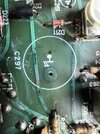
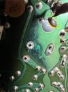
These pictures were taken from a radio I just opened up to start looking into a low frequency hum problem. From above the cap looked OK, although you could see some discoloration on the traces around it. Pulled it out and this what it left behind:
IMG_1721.jpegIMG_1722.jpeg
And that's after cleaning with alcohol.

I may be able to save these traces with some abrasives to get rid of the corrosion, or I may have to patch or rebuild them. Either way, they'll never be the same again.
 
Just to add a data point to the pro swap side.

These pictures were taken from a radio I just opened up to start looking into a low frequency hum problem. From above the cap looked OK, although you could see some discoloration on the traces around it. Pulled it out and this what it left behind:
View attachment 65956View attachment 65957
And that's after cleaning with alcohol.

I may be able to save these traces with some abrasives to get rid of the corrosion, or I may have to patch or rebuild them. Either way, they'll never be the same again.
Ooooh! I understand that!!!!
 
@nomadradio I hope you don't mind me asking a question. Not challenging at all... I'd just like to know your thinking and your experiences!

On that Tram Tuneup Doc.......

One change interests me......

ON the BA board... C625

it is originally 4 uF 150v. It is in the cathode circuit of the 6L6 audio tube.

You spec changing it to either 4.7uF or 1 uF (and THAT I understand! That bypass affects the gain at different frequencies!!!). What puzzles me is that you spec a 450 wv part.

I am just curious about that change for two reasons:

1) Will a 450 vcap fit in the same space?

2) I've seen a million 6L6 guitar amps that are cathode bias and the caps in those are usually in the 25 to 50v range.... as the bias that develops never gets any higher than that.

If you would be so kind, could you let me know your thinking on that? Have you seen a 6L6 short "anode to cathode" and damage that thing? Or is this more about "safety factor"?

Thanks for the info in that document !!!! Others and I appreciate it!

Bob
 
What puzzles me is that you spec a 450 wv part.
If that capacitor had been connected to the "protected" side of the modulator tube's cathode fuse, this wouldn't matter. The 160-Volt rating would be more than sufficient. The improved "BA+" board I sell has this capacitor safely protected by the fuse, and has a rating of 160V like the factory part.

The reason for boosting the voltage rating has to do with what happens if the 6L6GC tube shorts internally. Naturally, the fuse on the BA board will trip, but that capacitor is still connected to the tube's cathode. On the wrong side of that fuse. Even a dead-shorted tube can't put more than 400 Volts onto C625, so the 450V rating is safe. What persuaded me to do this was how often we would see the factory-original C625 exploded all over that corner of the BA board.

73
 

dxChat
Help Users
  • No one is chatting at the moment.