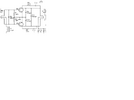
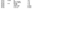
It does indeed look like the speech processor wiring and switch. It wasn't a stock item on the 120W or the 30W model, but it was easy to add them. They sound great with no processing, but it can help when in a pileup. Don't forget to check the Yahoo group because they have some extra files (including the right test points and the infamous D77 error) that will help you or others really align them perfectly.
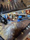
Here is one 120W model that I repaired recently. Note no speech processor. Enjoy that radio!
Welcome to WWDX! That is an interesting radio, I have never seen one of those before.