• You can now help support WorldwideDX when you shop on Amazon at no additional cost to you! Simply follow this Shop on Amazon link first and a portion of any purchase is sent to WorldwideDX to help with site costs.

Ranger SS3900EGHP American Spirit dead...

Hawkeye351

Well-Known Member
Jun 27, 2021
489
354
73
56
Got a Ranger SS3900EGHP (aka...American Spirit) on the desk today that's completely dead as far as receive and transmit.

Issues:
Powers on fine, all lights work, receive/transmit light switches when keying and unkeying as it should.

No receive, just light hash noise with volume wide open.
No transmit, not even a flicker when keyed.
No indication of output on monitor set on same channel.
No indication of receive when keying monitor radio on same channel.

VCO voltage will adjust smoothly from 1v up to over 8v, it's set at 1.65 for band A as service manual suggest.
The 10.240mhz crystal frequency is present and steady on pin 4 of the PLL at 10.239.9mhz.

I'll upgrade some pics in a bit.

Note:
There are signs of trace damage in several areas that were previously repaired, although not the way I would have fixed them, none the less there are no issues with the previous repairs other than cosmetically.

Nothing is getting hot, although the audio IC does get warm, not hot just warm.
 

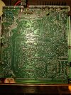
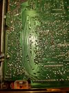
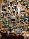
Trace side:
IMG_20240215_110449995_HDR.jpg

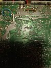
Regulator section:
IMG_20240215_110458780_HDR.jpg


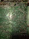
Final section:
IMG_20240215_110508743_HDR.jpg


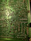
PLL section:
IMG_20240215_110516850_HDR.jpg


Mic AMP section:
IMG_20240215_110528349_HDR.jpg

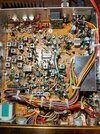
Component side:
IMG_20240215_110553276_HDR.jpg


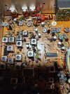
Final section:
IMG_20240215_110610420_HDR.jpg


Regulator section:
IMG_20240215_110619690_HDR.jpg


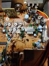
PLL section:
IMG_20240215_110628022_HDR.jpg
 
Frequencies from top bare lead of R74:
Band A, channel 1 = 17.8571mhz
Band B, channel 1 = 17.8571mhz
Band C, channel 1 = 16.6371mhz
Band D, channel 1 = 17.9171mhz
Band E, channel 1 = 17.8571mhz
Band F, channel 1 = 17.8571mhz


Band A, channel 40 = 16.5772mhz
Band B, channel 40 = 16.5772mhz
Band C, channel 40 = 17.9171mhz
Band D, channel 40 = 17.5971mhz
Band E, channel 40 = 17.8571mhz
Band F, channel 40 = 17.8571mhz (fluctuates between 17.84, 17.85, 17.86).

PLL voltages (taken on Band D, channel 20 in receive mode):
1 - 7.55
2 - 3.78
3 - 3.75
4 - 3.78
5 - 3.60
6 - 7.49
7 - 2.86
8 - 7.52
9 - 5.80
10 - 3.78
11 - 3.14
12 - 0.02
13 - 0.02
14 - 1.91
15 - 2.63
16 - 2.61
17 - 1.52
18 - 0.00

8v regulator (taken in receive mode):
Base - 12.75
Collector - 8.34
Emitter - 13.45

Audio IC (taken in receive mode):
1 - 12.73
2 - 6.75
3 - 0.00
4 - 0.00
5 - 1.12
6 - 1.12
7 - 0.00 (hums through speaker when touching probe).
8 - 0.00
9 - 6.44
10 - 13.44

Gonna volt out the Adders in a little bit, got errands to run.
 
The solder work on the bottom of the board is in the same area as that where the wax to keep the VCO stable is also - so some leaking or wicking of that wax can affect connections - so as you replace those caps - Power it up and key it up every now and then to make sure something is not going wrong as you work further into this to recover it
 
  • Like
Reactions: Hawkeye351
I see what you're talking about now. Solder joints in that area looks slightly lighter color than the rest of the solder on the board.

Is it my eyes, or does it look like someone has been soldering around the Adder chips?
 
someone has been soldering around the Adder chips?
Like, maybe using a soldering iron with an old-style AC heater and a two-wire line cord?

There will always be a little AC leakage from the power line to the tip of that kind of soldering iron. MOS transistors are easily damaged by line-leakage voltages. CMOS chips pretty well require an iron with a 3-prong plug. The third prong carries that tiny leakage current to ground, away from sensitive chips.

The frequency-change math is making no sense when you change bands. Really makes it sounds as if some random element has been thrown in the PLL on this one.

Pretty sure the lock detector on the PLL is pin 8. A meter won't reveal negative pulses on this pin. A PLL that's mostly, but not totally locked in will have pulses on this pin that can trip the receiver mute and transmit shutdown, even if it's just partly out of lock. Always best to check the out-of-lock detect voltage with a 'scope if you have one.

73
 
I noticed, the frequencies being presented when probing R74 are actually the VCO frequencies, not the mix frequency which the service manual calls for. Seems like the channel conversion was done wrong or the Adders aren't getting the 8v input they need to be mixed with the PLL frequencies.

Going over the schematic, I noticed a single diode in line with the 8v feed for the Adders. Gonna check that out when my caps get in.
 

dxChat
Help Users
  • No one is chatting at the moment.