Home now, looking at the CPU schematic again. I am going to think out loud for a minute.
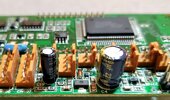
Something interesting is happening with that second shift register and the micro. U605 pins 5-8 go into a nasty resistor network, presumably turning 4 bits of digital into a programmable DC voltage. The output from it is fed into the micro Vref pin. The micro uses that pin with the comp(arator) pin to perform some programmed function.
Two things stand out here.
1) The comparator input comes from the main regulator output, but before the filter cap and isolated from it via diode. If the regulator loses power, this line goes low before the filter cap drains turning off the micro or shift registers and EEPROM. The 5v from the regulator, dropped by the diode, and passed through R629/R630 results in roughly 3.56v on the comp pin that goes away instantly on power loss.
2) With a 5v supply on the shift register, that resistor network could never output 3.56v even it all pins were high. It doesn’t take matricies and nodal circuit analysis to see that R616/R615, even if given the supply voltage of 5v, would only output 3.37v, and even that is impossible given the rest of the resistors. In other words, Vref is always lower than the comp line from the regulator.
So, we have a programmable reference voltage that gets compared against Vcomp which disappears fast upon power-down. Since this voltage disappears before the cap drains, I assume this comparator input triggers the write sequence when the power is turned off, and that cap (C604) keeps the chips hot long enough to finish that split-second write operation to the EEPROM.
This is, of course, mostly speculation. I set out to see if the circuitry supported power-off detection, and from what I see, I believe it does.
Just swap the cap, I'd bet it fixes it.
Edit: this might support NOT increasing the value of the pre-regulator cap. Increase the post-regulator cap all you want though.


") . Repetitious writes, or only on power cycle. Digikey does have the EE in stock, but the next question becomes whether or not it stores other data the micro reads each time it powers up, or if it only stores channel data. That will determine if you can simply swap out the EE or if it will require data transfer from the good blocks. I hope you have a 'scope!
. Repetitious writes, or only on power cycle. Digikey does have the EE in stock, but the next question becomes whether or not it stores other data the micro reads each time it powers up, or if it only stores channel data. That will determine if you can simply swap out the EE or if it will require data transfer from the good blocks. I hope you have a 'scope!