
Hi Chris,
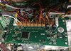
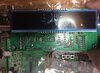
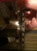
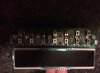
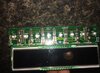
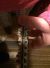
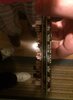
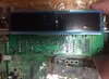
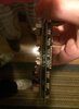
There are two holes one on each side of the pushbutton board. And two more on the CPU board, With two plastic spacers in between both boards. Between the two boards is a long plastic board looks like it is used to separate the two boards from touching each other. From what I can tell the pushbutton board has the 6 pins coming out of the back on each side and going thew the white connectors on the CPU board. So it looks like I just need to be very careful and separate the two boards from each other and reconnect the pushbutton board to the new CPU board? Here are a few pictures not sure if this will help or not. Chris, You don't know how much help you have given me thew the years and have also taught me a few things along the way. I forgot to mention help me save a lot of money I did not have to spend. For all of this, I am very grateful. Thank you once again, 73, I received a Massage from Greg, Here is what he had to say,
Yes, you can just use the old one. It just plugs into the processor. Just be careful to get it pluged in good. Greg
Attachments
-
 56555974_404642546992430_3789446149157421056_n.jpg64.8 KB · Views: 23
 -
 56608885_266558480891138_5397696700389261312_n.jpg49.1 KB · Views: 21
 -
 56644825_266873590860287_476991813693997056_n.jpg31.7 KB · Views: 20
 -
 56711139_2196317557073737_8391996789326086144_n.jpg32 KB · Views: 19
 -
 56716244_2271459589587454_6174556705418903552_n.jpg59.9 KB · Views: 18
 -
 56723880_535351613659010_4796925436758065152_n.jpg34.3 KB · Views: 19
 -
 56806432_1888549251251327_4902047518696669184_n.jpg32.2 KB · Views: 18
 -
 56823203_351192318836465_7853919017285713920_n.jpg51 KB · Views: 19
 -
 56960569_381024182491272_6923038731947474944_n.jpg66.9 KB · Views: 17
 -
 57101660_4752945068151525_5956850607095545856_n.jpg33 KB · Views: 20


") I for one would have not ever bought one knowing that parts were not available to fix them. I received an Email back from Galaxy telling me to call John. So I am going to call today and more than likely be told the part is no longer available. Will let you know. 73,
I for one would have not ever bought one knowing that parts were not available to fix them. I received an Email back from Galaxy telling me to call John. So I am going to call today and more than likely be told the part is no longer available. Will let you know. 73,