• You can now help support WorldwideDX when you shop on Amazon at no additional cost to you! Simply follow this Shop on Amazon link first and a portion of any purchase is sent to WorldwideDX to help with site costs.

RCI 2985DX low power

Lkaskel

Well-Known Member
Aug 4, 2017
373
301
73
59
I have an RCI 2985DX on the bench (today) with low output power (2w AM and 8w SSB). It does give me output on SSB but no modulation on AM. I removed the 11 meter jumper to reset it back to its defualt frequency range and began an alignment. The VCO/PLL aligned great. I moved onto the TX alignment and I get to the driver/final bias and it does not align well. The driver is supposed to be 10ma but it will only drop to 43ma at the lowest. The dual finals are supposed to be 100ma combined and have 2 adjustments. VR 12 has no effect on the reading and VR 11 goes from 128ma to over 400ma. This radio has the 1966 driver and 2312 finals. I stopped at this point. Have you seen this? So, low power, no AM modulation and strange bias.....

Thanks!!
 

Hmm. Sounds like a radio that had a final and/or driver fail. Someone ignored the damaged bias diode and bias trimpot and just changed transistors. They may have even checked the driver and finals before replacing them.

Sometimes the new transistors survive this quick-and-dirty method. Sometimes they don't.

Just sounds like there is collateral damage to components in the base circuits of the driver and final both. A shorted driver and/or final can push a surge into the other parts in the base circuit and blow them out. Makes the replacement transistor behave all wrong, if it survives at all.

Every fixed resistor, choke, trimpot and diode in each base circuit is suspect until it checks okay or gets replaced.

73
 
  • Like
Reactions: NZ8N
Yes, I had this problem before. Months ago on a few of these
types radios. just a "hunch" I have.
sounds like maybe problem in the series amplitude modulator
circuit. (Q66/Q67)
SSB n FM will still work if a voltage reading is present.
check the voltage at the "shorting board"
TP7, 8, 9. to board ground. in SSB should go up to around 12 V.
in AM voltage around 4 to 6 volts, depending on the power setting.
this voltage modulates in AM Mode.
 
I should add, do this first...... remove the "shorting board"
to isolate the RF driver and output from this test.
test the voltages at TP9. the 6 V or so in AM Mode, and 12 V in SSB
mode.
 
Thanks for some of your thoughts here. I just got back in town and am working on this again. The driver tested fine but the finals did not. I replaced the finals and the trim pots. The finals now will adjust to 100ma as expected. I also replaced the driver trim pot and it will only adjust down to 25ma (it calls for 10ma). With the radio adjusted to 25ma driver, 100ma combined finals (~50ma each), AM set to 6 volts and USB set to 12.5 I am still having issues. In AM the radio will key to 5 watts for 1 second and then drop to 2 watts. I also replaced the AM regulator (a 754) with a TIP36. Any thoughts here?
 
all the schematics of that radio I see show just one final RF 2312.
where can I see this version with 2 finals?
I worked on the mosfet versions, very very similar.

when You key down in AM, does the 6 V at the shorting board
drop down when the RF output drops.?
 
So, I fixed the power problem late last night. The driver bias is still at 25ma and will not go lower but I am willing to accept that for now. What I found was that one of the finals was bad. While it would align with a 50ma bias setting (100ma combined) it would fail once the radio was in TX mode. How I trouble shot this was to de-solder one of the finals and try to transmit. When I did this the 1st time the radio worked at 1/2 power. I then tried the other final and when I transmitted the radio would give 1/2 power for a moment and then drop to zero watts. I switched out the final with another 1969 and it worked perfectly. WOW!!!!

Now to the schematic question. I had a heck of a time finding the right one. While the attached schematic is not for the correct board version number it is correct in the overall design. I did verify every part in the finals section to be sure that t hey were the same as represented in this schematic.

Any thoughts on the driver bias?

Thanks for everyones help!!!
 

Attachments

  • RCI - EPT695012B schematic.pdf
    489.7 KB · Views: 5
If the bias diode D93 tests OK, change VR13 to a 2K or change R276 to a 220 ohm half watt to give the driver bias more range on the low end.
Are you sure it calls for 10ma? On most radios the driver bias calls for 25-35ma.
 
  • Like
Reactions: Shadetree Mechanic
If the bias diode D93 tests OK, change VR13 to a 2K or change R276 to a 220 ohm half watt to give the driver bias more range on the low end.
Are you sure it calls for 10ma? On most radios the driver bias calls for 25-35ma.
I am not 100% as I am not sure I have the exact alignment guide. Attached is what I am making that decission on.
 

Attachments

  • RCI 2985 - 2995 Service Manual from 2001.pdf
    3.8 MB · Views: 4
By golly it does say 10ma.
An open or damaged bias diode can make the bias control not want to adjust low enough but I have emcountered on some models of Galaxy/Ranger radios where the factory resistor values on the bias circuit are incorrect. Check and even change D93 first and if it still won't dial down, change one of the resistors I mentioned.
 
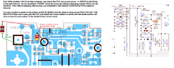
I noticed a similar problem on a 2950/2970 main board a
few months ago. In the driver transistor bias circuit.
I added a 100k resistor to ground.
- - from that post:

"So looking at the schematic at Q62 there is no resistor going to ground after
bias adj pot VR13 to make a correct adjustable voltage divider.
So I added a 100k ohm resistor to ground at this spot, to make it just like
the bias circuit on the at Q62 on the RCI-2995."
 
That lack of a divider goes back into the early bipolar days - the Diode took most of the current but would also provide problems when sitting at idle - in TX mode but no signal - the ability for the Driver circuit to take RF from even the 10.240 or 10.7 IF - sent to the mixer - can blow the 2166 if the tuneup done to it was "overpeaked" - even the SO42P - enough leakage can latch the Driver - a 2166 - being such a high gain - into the on-state and just sit there throwing a 10mhz carrier from the IF that leaked thru the mixer.

You'd see it on the RF meter, but you would not know or couldn't know - you had to figure out how the radio sitting next to it, was deaf to it unless you were able to crossover some IF into the RX strip into the monitor radio to hear the result - just carrier - no audio - because the mixer leaked enough on down to the driver.
 

dxChat
Help Users
  • No one is chatting at the moment.