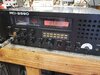
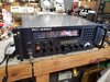
I got hold of another 2990, and boy...there's been some fingers in this radio! I've been trying to find a service manual to properly do a full alignment, an am wondering what mobile would have the same chassis?
Thanks,
Dave
Thanks,
Dave

") .
.Does anyone make a front panel overlay?
Haven't seen one for that radio.
Best favor you can do for it is to unload the original power transformer/rectifier/filter/regulator from the thing. A 300-Watt switchmode "brick" power supply will run the radio just fine, and protect it from runaway unregulated 24 Volts. The factory power supply is famous for popping the computer board when this happens. And that board is made from unobtanium.
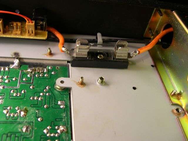
Second-biggest favor is adding a 4-Amp fuse to the power wire feeding the radio circuit board.
Most people wouldn't run a mobile radio from a 25-Amp power supply without a fuse. But that's what the factory delivered.
73
Got a replacement got lucky that part is good to.go now I got.a problem with receive when I touch the board at R145 receive is normal when I leave off it dies out and the same if I touch the top of the resistors it will pick up I got this a few months back at a saleIt contains two switch contacts. Close to zero ohms when the contact points touch, open circuit when they don't.
It's a "momentary" quadrature encoder. No continuity through it until you click it. One of the two contacts closes before the other. The computer can tell which direction you turned it by which one or the other of the two contacts closes first.
The contacts have a tendency to "bounce", that is the contacts are springy and will make/break multiple times when clicked. The computer is supposed to sort this out, but doesn't do it all that well. Even a new radio will jump multiple channels with one click, or change frequencies the wrong way if turned too quickly.
Takes an oscilloscope, power source and resistor to test it. A meter alone just can't.
73