
You are using an out of date browser. It may not display this or other websites correctly.
You should upgrade or use an alternative browser.
You should upgrade or use an alternative browser.
-
You can now help support WorldwideDX when you shop on Amazon at no additional cost to you! Simply follow this Shop on Amazon link first and a portion of any purchase is sent to WorldwideDX to help with site costs.
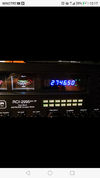
RCI-2995 DX CF s-meter behaviour
- Thread starter ALANFede
- Start date
Hi Alanfede,
One possibility is the meter calibration/adjustment for receive. On the 2995 there are separate adjustments for AM (VR1) and SSB (VR2). It is possible that someone turned VR2. If it is a used radio it would be a good idea to have it aligned so you know that everything in it is set up correctly.
One possibility is the meter calibration/adjustment for receive. On the 2995 there are separate adjustments for AM (VR1) and SSB (VR2). It is possible that someone turned VR2. If it is a used radio it would be a good idea to have it aligned so you know that everything in it is set up correctly.
Thanks @Lkaskel - for chiming in. Got sidetracked on several projects...
VR2 is SSB meter adjust - but if LSB works, and USB shows full carrier - it may mean several messes are underway.
@ALANFede - locate L11 and L12 - and VR1 and VR2 - VR2 controls the meter - while L11 and L12 "center" the SSB signal to be amplified.
The main fear? The Diode Routing Matrix used on this type of SMD board - uses "combo" diodes (SMD Packages with more than one diode tied Anode or Cathode point) and direct or route power thru them as "AND" / OR gates to achieve the proper PNP / NPN driver switch to turn on a section and all others are following their "instruction" on the array of diodes from that switch.
The Static pokes and switch to power supply - the SOT (SMD) package is only as good as the operator can take the precautions of static pokes on the knobs while in operation.
Ok, the radio has two IF's one for AM and FM the other for IF SSB - the AM side uses the SAME IF strip for output (Detector) - so SSB and AM are together to a specific point.

Then things can go bad.

As it works, the radio uses a set of high-gain transistors, each one tied to that Diode Matrix - per DIODE, to act as a switch to turn on power or switch on ground - thru a SMD to make the section it powers or sinks current to make it "enabled" - and it uses that Diode Matrix of diode SMD SOT and even discrete (for wattage) to route power to turn on that specific section.
Two types are;
RN1403 - a NPN device
RN2403 - a PNP device
Let's hope it just needs L11 and L12 realigned.
However, to obtain anything for L11 and L12 - the output of the combined IF strip before it heads off to handle FM and AM / SSB - if that output is off or has a defective part - L11 and L12 will not allow you to tune USB if the FL series of crystals used to find and filter down to the USB or LSB sides of an AM band - is out of whack.
That will require more tuning and adjustment that most can easily work thru from home and simple equipment.

There is an error in the Datasheets...

VR2 is SSB meter adjust - but if LSB works, and USB shows full carrier - it may mean several messes are underway.
@ALANFede - locate L11 and L12 - and VR1 and VR2 - VR2 controls the meter - while L11 and L12 "center" the SSB signal to be amplified.
The main fear? The Diode Routing Matrix used on this type of SMD board - uses "combo" diodes (SMD Packages with more than one diode tied Anode or Cathode point) and direct or route power thru them as "AND" / OR gates to achieve the proper PNP / NPN driver switch to turn on a section and all others are following their "instruction" on the array of diodes from that switch.
The Static pokes and switch to power supply - the SOT (SMD) package is only as good as the operator can take the precautions of static pokes on the knobs while in operation.
Ok, the radio has two IF's one for AM and FM the other for IF SSB - the AM side uses the SAME IF strip for output (Detector) - so SSB and AM are together to a specific point.
Then things can go bad.
As it works, the radio uses a set of high-gain transistors, each one tied to that Diode Matrix - per DIODE, to act as a switch to turn on power or switch on ground - thru a SMD to make the section it powers or sinks current to make it "enabled" - and it uses that Diode Matrix of diode SMD SOT and even discrete (for wattage) to route power to turn on that specific section.
Two types are;
RN1403 - a NPN device
RN2403 - a PNP device
Let's hope it just needs L11 and L12 realigned.
However, to obtain anything for L11 and L12 - the output of the combined IF strip before it heads off to handle FM and AM / SSB - if that output is off or has a defective part - L11 and L12 will not allow you to tune USB if the FL series of crystals used to find and filter down to the USB or LSB sides of an AM band - is out of whack.
That will require more tuning and adjustment that most can easily work thru from home and simple equipment.
There is an error in the Datasheets...
Last edited:

Wow! Thanks so much for the support. I'm so sorry, but I forgot a detail about the S-meter: when I switch from AM to USB the needle reaches the maximum scale (you can hear the touch) and then, it returns to its normal position (to zero) and works correctly. The same thing happens from CW to LSB mode.
Oh ok!
Thats better (*whew - puts away the encyclopedias for now*)
When it "snaps the needle" like that it's the radio itself finding places to "dump" energy it has for one mode, a means to turn off that section - and turn on another when you switch to a different mode.
 Some the needle jump is normal - but if you hear a *tink* and see the needle buried in the side, then you have a serious problem that you'll need to fix sooner than later - that *tink* refers to the sound an analog needle makes when it hits full stop on the opposite side on the meter. It's not good for it, as well as the radio telling you it's got something going on.
Thats better (*whew - puts away the encyclopedias for now*)
When it "snaps the needle" like that it's the radio itself finding places to "dump" energy it has for one mode, a means to turn off that section - and turn on another when you switch to a different mode.

Thank you very much for your support, this exchange of experiences is great. I also own a Galaxi Saturn and comparing the diagram you sent me and that of the Saturn I saw that as far as the s-meter section is concerned, they are identical. The Saturn however does not have the same behavior. Movement is imperceptible. The ranger 2995 when switched from AM to USB has a violent and fast movement and the indicator slams against the limit, with a resounding "teak", and then works correctly. Personally I don't find this behavior correct, because if I continued to operate normally, switching the various emission modes, the life of that indicator would be somewhat limited. There appears to be some charge that in switching discharges in the movement of the s-meter. This does not convince me, sorry. If you own an RCI-2995, do your equipment behave the same way ?! I sent an email to the Ranger, with no reply. So, via WhatsApp line I contacted them by sending an explanatory video. They replied that it's normal ... Well ... I'm not persuaded. Thanks for your attention and help.
Attachments
Well, to take you down a rabbit hole - but only to let you see - then you can decide to climb back out or pursue this further...
The reason I showed you what I did was to bring attention to the way the radio handles and processes the signals.
As you have been introduced to - the Galaxy Saturn is not far different from the later model cousin - pretty much the same layout and technology, except the parts that use the technology are highly advanced - by several generations.
Transistors these days are much faster and use a different die layout design to make them work - so the older days of PN then add another P to make a PNP and the same can be said for NPN - those days of the accretion/diffusion process has changes more over to a expose diffusion process and masking that although the part number is correct - the performance of that part does vary from the older days. The junction types change the behavior of the once analog device into a more linear digital switch - lower noise and better layouts give the part an edge in performance that tends to make the part overperform in the newer boards.
So, while you enjoy the "new radio smell" and the performance that it provides, the slamming of the needle is showing you a limitation in the design, but not the product.
You can't just put older parts in and expect the radio to recover - no; that won't happen - the layering and pontification of the newer parts and their performance - makes the interfacing difficult.
For Educational Purposes Only


Part of the issue is IC1 - and it's later SMD/Analog DIP cousin using the newer SMD layout inside - makes the linearity and operational character faster - and trigger happy - which is a performance improvement by the modification of the input die layout of the pins - they have less capacitive and inductive reactive component structure so that affects the way the trigger/linear operation - works in a circuit they tuned and designed to offset a now-seen-as-a-quirk reactive element from the earlier generations.
The reason I mentioned earlier about the conversion process and showed that part of the circuit - was due to the changing or shift in IF frequency window to above and just below the CENTER IF frequency - USB/LSB and the AM - USB and LSB signals are extracted from 27MHYz (for example) and brought to a 10.7MHz (thereabouts) frequency - but you also have an AM signal that is imaged - and has a carrier component - this is important to know when trying to find out if you have a slow VCO or a bad IF filter crystal network.
A slow switching VCO blips the meter because to obtain the IF image of the SSB signals it uses a high - gain amplifier and the AGC side of IC1 - controls the LEVEL of gain.
IF the switching process, it's not supposed to be noisy, but the switch happens so quickly the IC1 sees a carrier - from its own IF - and so the USB sides conversion process - being so much closer to the CENTER of an AM carrier Image - having to start filtering out that "carrier" you see that blip.
That is the best way I can describe it.
TO fix that? tweaking - but the opinions of how to do it is comparing apples to oranges, one tech might adjust the AGC caps and actually lower one value and add in another one piggybacking the cap with a value of 1/2 the original cap used. Another would just offset the USB coil and perhaps the input level strength (signal strength) of the SSB side as tradeoffs to fix a overzealous AGC caused by the new fanged IC1 replacement and upgraded part with the same pinout and functionality - and call it LM324.
I'll let you gather your wits and see if you even want to know more...

Don't worry about the rabbits' watch - I took the batteries out a long time ago, it's been 5 o'clock somewhere, nearly forever...
The reason I showed you what I did was to bring attention to the way the radio handles and processes the signals.
As you have been introduced to - the Galaxy Saturn is not far different from the later model cousin - pretty much the same layout and technology, except the parts that use the technology are highly advanced - by several generations.
Transistors these days are much faster and use a different die layout design to make them work - so the older days of PN then add another P to make a PNP and the same can be said for NPN - those days of the accretion/diffusion process has changes more over to a expose diffusion process and masking that although the part number is correct - the performance of that part does vary from the older days. The junction types change the behavior of the once analog device into a more linear digital switch - lower noise and better layouts give the part an edge in performance that tends to make the part overperform in the newer boards.
So, while you enjoy the "new radio smell" and the performance that it provides, the slamming of the needle is showing you a limitation in the design, but not the product.
You can't just put older parts in and expect the radio to recover - no; that won't happen - the layering and pontification of the newer parts and their performance - makes the interfacing difficult.
For Educational Purposes Only
Part of the issue is IC1 - and it's later SMD/Analog DIP cousin using the newer SMD layout inside - makes the linearity and operational character faster - and trigger happy - which is a performance improvement by the modification of the input die layout of the pins - they have less capacitive and inductive reactive component structure so that affects the way the trigger/linear operation - works in a circuit they tuned and designed to offset a now-seen-as-a-quirk reactive element from the earlier generations.
- Study the schematics of two different parts - one top from 2012 and the other from 2005 lower - the differences are not in the schematic - which tends to force the part to stay within a given Part numbering - in this case an LM324 - but the die to make it and the process used to make the die for the thing to work is advanced by several degrees.
- So this changes the PRFORMANCE the part has, so to make the part operate liek it's older cousin it is supposed to replace - requires a new level of thinking and adaptation of the older platform technology to handle the newer part at an interface level.
The reason I mentioned earlier about the conversion process and showed that part of the circuit - was due to the changing or shift in IF frequency window to above and just below the CENTER IF frequency - USB/LSB and the AM - USB and LSB signals are extracted from 27MHYz (for example) and brought to a 10.7MHz (thereabouts) frequency - but you also have an AM signal that is imaged - and has a carrier component - this is important to know when trying to find out if you have a slow VCO or a bad IF filter crystal network.
A slow switching VCO blips the meter because to obtain the IF image of the SSB signals it uses a high - gain amplifier and the AGC side of IC1 - controls the LEVEL of gain.
IF the switching process, it's not supposed to be noisy, but the switch happens so quickly the IC1 sees a carrier - from its own IF - and so the USB sides conversion process - being so much closer to the CENTER of an AM carrier Image - having to start filtering out that "carrier" you see that blip.
That is the best way I can describe it.
TO fix that? tweaking - but the opinions of how to do it is comparing apples to oranges, one tech might adjust the AGC caps and actually lower one value and add in another one piggybacking the cap with a value of 1/2 the original cap used. Another would just offset the USB coil and perhaps the input level strength (signal strength) of the SSB side as tradeoffs to fix a overzealous AGC caused by the new fanged IC1 replacement and upgraded part with the same pinout and functionality - and call it LM324.
I'll let you gather your wits and see if you even want to know more...
Don't worry about the rabbits' watch - I took the batteries out a long time ago, it's been 5 o'clock somewhere, nearly forever...
Last edited:
Well, to take you down a rabbit hole - but only to let you see - then you can decide to climb back out or pursue this further...
The reason I showed you what I did was to bring attention to the way the radio handles and processes the signals.
As you have been introduced to - the Galaxy Saturn is not far different from the later model cousin - pretty much the same layout and technology, except the parts that use the technology are highly advanced - by several generations.
Transistors these days are much faster and use a different die layout design to make them work - so the older days of PN then add another P to make a PNP and the same can be said for NPN - those days of the accretion/diffusion process has changes more over to a expose diffusion process and masking that although the part number is correct - the performance of that part does vary from the older days. The junction types change the behavior of the once analog device into a more linear digital switch - lower noise and better layouts give the part an edge in performance that tends to make the part overperform in the newer boards.
So, while you enjoy the "new radio smell" and the performance that it provides, the slamming of the needle is showing you a limitation in the design, but not the product.
You can't just put older parts in and expect the radio to recover - no; that won't happen - the layering and pontification of the newer parts and their performance - makes the interfacing difficult.
For Educational Purposes Only
View attachment 57835
View attachment 57836
Part of the issue is IC1 - and it's later SMD/Analog DIP cousin using the newer SMD layout inside - makes the linearity and operational character faster - and trigger happy - which is a performance improvement by the modification of the input die layout of the pins - they have less capacitive and inductive reactive component structure so that affects the way the trigger/linear operation - works in a circuit they tuned and designed to offset a now-seen-as-a-quirk reactive element from the earlier generations.
So, what do you do? Not much - but what is DOES show, is the way the radio switches the IF frequency - and how quicky it stabilizes.
- Study the schematics of two different parts - one top from 2012 and the other from 2005 lower - the differences are not in the schematic - which tends to force the part to stay within a given Part numbering - in this case an LM324 - but the die to make it and the process used to make the die for the thing to work is advanced by several degrees.
- So this changes the PRFORMANCE the part has, so to make the part operate liek it's older cousin it is supposed to replace - requires a new level of thinking and adaptation of the older platform technology to handle the newer part at an interface level.
The reason I mentioned earlier about the conversion process and showed that part of the circuit - was due to the changing or shift in IF frequency window to above and just below the CENTER IF frequency - USB/LSB and the AM - USB and LSB signals are extracted from 27MHYz (for example) and brought to a 10.7MHz (thereabouts) frequency - but you also have an AM signal that is imaged - and has a carrier component - this is important to know when trying to find out if you have a slow VCO or a bad IF filter crystal network.
A slow switching VCO blips the meter because to obtain the IF image of the SSB signals it uses a high - gain amplifier and the AGC side of IC1 - controls the LEVEL of gain.
IF the switching process, it's not supposed to be noisy, but the switch happens so quickly the IC1 sees a carrier - from its own IF - and so the USB sides conversion process - being so much closer to the CENTER of an AM carrier Image - having to start filtering out that "carrier" you see that blip.
That is the best way I can describe it.
TO fix that? tweaking - but the opinions of how to do it is comparing apples to oranges, one tech might adjust the AGC caps and actually lower one value and add in another one piggybacking the cap with a value of 1/2 the original cap used. Another would just offset the USB coil and perhaps the input level strength (signal strength) of the SSB side as tradeoffs to fix a overzealous AGC caused by the new fanged IC1 replacement and upgraded part with the same pinout and functionality - and call it LM324.
I'll let you gather your wits and see if you even want to know more...
Don't worry about the rabbits' watch - I took the batteries out a long time ago, it's been 5 o'clock somewhere, nearly forever...
Hello Handy Andy, Thank you very much for helping me discover this new radio for me. In fact, every time I use it I discover an aspect that I personally find not very normal. For example: high-pitched noise is always present in all emission modes, for the entire frequency range of the radio, which is also present when receiving correspondents. It reduces proportionally with the intensity of the correspondent, but in low-level emissions to be able to improve understanding, I have to act by lowering the RF Gain and Audio volume to improve the S / N ratio. In the old Saturn, by acting on the Tone command it was possible to cut the high frequencies and improve reception, in this apparatus it is not present. Is the presence of this noise normal, which I find annoying, or is it a problem?
One more thing ... What can you tell me about the Q12 And Q13 transistors? Thanks for the support. Federico
One more thing ... What can you tell me about the Q12 And Q13 transistors? Thanks for the support. Federico
An example to explain me better: it's like always being in FM mode. thank youHello Handy Andy, Thank you very much for helping me discover this new radio for me. In fact, every time I use it I discover an aspect that I personally find not very normal. For example: high-pitched noise is always present in all emission modes, for the entire frequency range of the radio, which is also present when receiving correspondents. It reduces proportionally with the intensity of the correspondent, but in low-level emissions to be able to improve understanding, I have to act by lowering the RF Gain and Audio volume to improve the S / N ratio. In the old Saturn, by acting on the Tone command it was possible to cut the high frequencies and improve reception, in this apparatus it is not present. Is the presence of this noise normal, which I find annoying, or is it a problem?
One more thing ... What can you tell me about the Q12 And Q13 transistors? Thanks for the support. Federico
For what it’s worth, I’ve got the exact same radio you have and I’m experiencing the exact same needle behaviour. I was also wondering if normal. After your testimony, I’m now convinced it is. Bought mine 2 months ago from a shop in Brooklyn USA.Oh ok!
Thats better (*whew - puts away the encyclopedias for now*)
When it "snaps the needle" like that it's the radio itself finding places to "dump" energy it has for one mode, a means to turn off that section - and turn on another when you switch to a different mode.
Some the needle jump is normal - but if you hear a *tink* and see the needle buried in the side, then you have a serious problem that you'll need to fix sooner than later - that *tink* refers to the sound an analog needle makes when it hits full stop on the opposite side on the meter. It's not good for it, as well as the radio telling you it's got something going on.
Bought my Ranger from State line CB shop in Florida, and it's brand New,does the exact same thing, Great radio and Solid on SSB!!For what it’s worth, I’ve got the exact same radio you have and I’m experiencing the exact same needle behaviour. I was also wondering if normal. After your testimony, I’m now convinced it is. Bought mine 2 months ago from a shop in Brooklyn USA.
No I didn’t noticed it. Using it with 400 LMR coax hooked to a Sirio 2008.Thanks for your experience! Did you also notice the loud "white" noise in reception, also present when listening to correspondents ?! Thank you
It could be you’re getting some HF interference through your coax.
I love this radio. One thing I need to do is switch the power supply to 220v (it has a switch inside) and swap the fuse in the back for a 3 amp 220v. That way I won’t need the external converter.
dxChat
- No one is chatting at the moment.