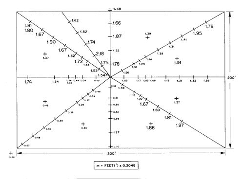
I went back and read the article more slowly. It seems the counterpoise and the ground screen were similar in properties. They were both superior to the buried radial system, and both apparently had measurable capacitance throughout the networks, but superior capacitance above those parts of the earth that had greater conductivity.

-
You can now help support WorldwideDX when you shop on Amazon at no additional cost to you! Simply follow this Shop on Amazon link first and a portion of any purchase is sent to WorldwideDX to help with site costs.
-
A Winner has been chosen for the 2026 July 4th Retevis RA89R Giveaway! Click Here to see who won!
Regarding antennas, what does counterpoise mean?
- Thread starter Marconi
- Start date