• You can now help support WorldwideDX when you shop on Amazon at no additional cost to you! Simply follow this Shop on Amazon link first and a portion of any purchase is sent to WorldwideDX to help with site costs.

[SOLVED] Clarifier unlocked. Voltage drops by 0.04v on transmit. Possible remedy?

doffo

Sr. Member
Oct 14, 2012
708
647
103
Hello,

It really didn't dawn on me until yesterday when i did the clarifier unlock on an old Realistic TRC-451. I have a Uniden Grant XL under my desk with its clarifier unlocked as well. When I go to transmit on one radio, and adjust the clarifier on the other, I can get it right on. But when I transmit from the radio on that I was adjusting the clarifier on, it is off on the radio receiving....

So that is when i grabbed a multimeter, and measured the voltage from the point the clarifier was pulling from. On Idle, the voltage was at 8.28 volts.. When you transmit from the same radio, it dropped down to 8.24 volts. Not a whole lot, but enough that it will be off in Hertz from where you are listening at.
It is for sure better than a radio without its clarifier unlocked and transmitting way off frequency. At this point I was splitting hairs and trying to get it exact.

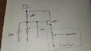
Is it possible to add a small board/circuit by itself that will take in the 12v, and put it to a set voltage of 8.00v? This way no matter what if you are listening or transmit, it keeps it locked on 8.00v.

Again, its probably very minimal change, but enough that I am now curious about it.

Thanks for reading. Hope ya'll had a great day.
 

I don't think it is very important to have it exactly 8v as long as the voltage is the same in RX and TX.

Avoid cheap regulators like the 7808 as they are terrible at ripple rejection and the modulated audio could carry through to the tuning varactor. There are precision regulators like the TL431, but that's probably overkill here.

The most common approach is to use a zener followed by a capacitance multiplier. 8.7v is right in the transition region between zener tunneling and avalanche breakdown and things get noisy there. If you can tolerate a slightly lower voltage, go with an 8.2v zener, or, if that's too low, go up to 9.1v. The Vbe junction of the NPN will drop about .7v of that, so you will get 7.5v or 8.4v that way. In any event, 8.7v is probably the noisiest zener you can buy,

You want to aim for about 8mA zener current to get above the knee and minimize noise.

Here is a simple circuit that will get you a voltage stable enough to use, I recommend an 8.2v zener.
 

Attachments

  • 20260304_192326.jpg
    20260304_192326.jpg
    1.3 MB · Views: 10
Last edited:
I don't think it is very important to have it exactly 8v as long as the voltage is the same in RX and TX.

Avoid cheap regulators like the 7808 as they are terrible at ripple rejection and the modulated audio could carry through to the tuning varactor. There are precision regulators like the TL431, but that's probably overkill here.

The most common approach is to use a zener followed by a capacitance multiplier. 8.7v is right in the transition region between zener tunneling and avalanche breakdown and things get noisy there. If you can tolerate a slightly lower voltage, go with an 8.2v zener, or, if that's too low, go up to 9.1v. The Vbe junction of the NPN will drop about .7v of that, so you will get 7.5v or 8.4v that way. In any event, 8.7v is probably the noisiest zener you can buy,

You want to aim for about 8mA zener current to get above the knee and minimize flicker noise.

Here is a simple circuit that will get you a voltage stable enough to use, I recommend an 8.2v zener.
Appreciate the input! It all kinda goes over my head, but now I realize that a simple 7808 will not be up to the task... In all honesty its ok on the air, but if one really wanted to keep it stable and not move between receive and transmit, that circuit design you drew up would be ideal!
 
Very easy mod. . . . .

You need to compare the difference between your TRC-451 and the TRC-465.

The voltage regulator circuit for the TX and RX in the TRC-465 had been
up-graded with IC4 (L7808CV, 7808, LM7808), and related parts
.
Do not confuse it with the IC4 in the TRC-451.

•• In the TRC-451 ... TR34, TR35, and related parts are the regulator
circuit, and they will remain in the radio.
•• In the TRC-465 ... The 7808 and related parts are the regulator
circuit, and are the only three parts to be used
in the TRC-451. (2 caps, a 7808, and wire)

NEW PARTS NEEDED:
1 each - 7808 to include mounting hardware and isolation pad
2 each - capacitors C118 & C119 (Using TRC-465 part numbers, see
instructions "Step 3")
2 each - wires (But maybe as many as 4 wires cut to length needed.)

The data sheet information for the 7808:

INSTRUCTIONS:
◙ Unsolder ONLY one wire, prep and install 7808, solder the 3 (or 4) wires to the radio.


1. The radio will remain with all it's parts regulator parts, only adding the 7808 and related parts to only regulate the Clarifier Potentiometer. All
of the following steps can be found in the schematic for the TRC-465 of the IC4 (7808) and its two capacitors (C118 & C119) forming the voltage regulator.

2. Unsolder the Positive wire from the CLARIFIER Potentiometer at the BOARD, not the Potentiometer.

(This is how to use the 7808 regulator "Step 3".)
3. Using two electrolytic capacitors (for C118 & C119), of the same value, anywhere from 10uf/16v to 1000uf/25. These caps filter the ripple and warbling of the audio transmit and should always be used with an 78XX regulator.
*****(Sorry you didn't know this Brandon.)*****

(The following capacitor connections for C118 and C119 are all the same just mounted in different places. either to the 7808 or to the board and clarifier.)

a. With one of the capacitors (C118) soldered:
* 1. To the 7808 from pin1 (positive output) to pin2 (ground)
OR
2. To the the outside positive pin of the clarifier potentiometer and
the other side soldered to ground. (This is where I think the best place to filter the voltage going to the Clarifier is.)

b. With the other capacitor (C119) soldered:
* 1. To the 7808 from pin2 (ground) to pin3 (positive input) being as close to the 7808 as possible.
OR
2. If you can find a spot on the board, with 2 or 3 holes open, and are very close to where the 7808 would get mounted. With a 3rd wire, run the 7808 pin3 (positive input) to the positive side of the capacitor soldered on the (radio board) with the other negative end of the capacitor soldered to board ground.
* This would mean that at "Step 5" pin3 of the 7808 would end up with two wires going to it (your choice):
a. Two wires from pin3 of the 7808; one to the capacitor, the 2nd to the positive of the "ON/OFF" switch.
OR
b. Two wires to the positive side of the capacitor; one to the 7808, the other to the "ON/OFF" switch.
***c. At this point you should have the 7808 with two capacitors soldered to it, or one on the board and the other at the Clarifier Potentiometer voltage input. (or a mix of both once you decide how the schematic is.)
*** Make sure you match the polarity of the 2 capacitors to the 7808 (pins "1 & 3" are Positive polarity and pin "2 & the mounting stub" are board Negative polarity.

4. Measure all the wire lengths needed, for the following steps, from where the 7808 will be mounted to where the wires have to go. If the length at "Step 6" doesn't reach ..... replace with new wire of proper length.

5. Connect two wires to the 7808, one each at pins 2 & 3. (see "Step 3b2")

6. Solder the Positive wire from the CLARIFIER Potentiometer to Pin1 of the 7808. (The wire that was unsoldered at "Step 2".)

7. Solder the wire from pin3 on the 7808 to the ON/OFF switch to come on with the radio. (see "Step3b2" is needed)

8. Solder the wire from pin2 (ground) of the 7808 to board ground.

9. Insulate and mount the 7808 to the either side of the frame so that it can be used as a heat-sink (just like installing a driver or final)., and it does not ground to the frame.

Disclaimer: YOU ARE RESPONSIBLE FOR YOUR OWN MISTAKES.....
It's all there in the schematic of the TRC-465 (IC4 circuit).....
Just 3 parts and maybe 4 wires.....
Only by-passing the TRC-451 regulator with a 7808 to the clarifier.....


My 2¢. . . . .
73
 

Attachments

  • Like
Reactions: doffo and MKwrench
Very much appreciated! My trusty Cobra 146 GTL out in the mobile will be brought in as well for some attention. :)
 
You should always solder the capacitors as close as possible to the 78xx series regulator, even more so in a rf rich environment,
a couple of tantalum caps directly to the regulator legs is good practice,

78xx series regs are poor performers if you are dealing with high end HIFI but they are found in CB & HF radios supplying voltage to various circuits,
usually the radios have chokes & filter caps before the supply reaches the regulator.
 
  • Like
Reactions: Gman
Happy to report that using the 2 capacitors and a 7808 worked a treat. :)

Just to be sure I wasn't imagining things, I hooked back up the other TRC-451, and it was off like i mentioned earlier. Put back my Cobra 146 GTL (The one I put the 7808 in.), and it is much better.

I ended up using a spot near the back and a big ol 1000uf 35v capacitors.

Please let me know if the way I did it is a no go or I should go about it a different way next time. (Surely a physically smaller capacitor would be ideal lol.)

Cobra 146 GTL 7808 1.jpg

Cobra 146 GTL 7808 board under.jpg
 

dxChat
Help Users
  • No one is chatting at the moment.
  • @ heartbreaker3473:
    Hello gentlemen and Ladies. I have the dreaded RCI-2990 receive issue where my radio gets distorted when people get close to my location. I found the C90 Capacitor, but I can not for the life of me find the C89 capacitor. Can or does anyone have a picture of the exact location of C89 ? Thank you in advance, Wes
  • @ AudioShockwav:
    Wes, it's better if you start a thread on the main forum, more people are going to see your question.
  • @ heartbreaker3473:
    Okay, sorry, will put in a forum
  • @ heartbreaker3473:
    I put it in the general disscution help area and started a new thread. Thank you for letting me know.