• You can now help support WorldwideDX when you shop on Amazon at no additional cost to you! Simply follow this Shop on Amazon link first and a portion of any purchase is sent to WorldwideDX to help with site costs.

Stryker SR-94HPC Noise Blanker and AMC

Shockwave

Sr. Member
Sep 19, 2009
3,809
3,381
273
Has anyone else noticed that that NB switch on this radio acts exactly like an Automatic Noise Limiter? As soon as you turn it on, it changes the sound of everything in the receiver. You hear a drop in high frequency response and a slight bit of distortion associated with the clipping action of the limiter. I have never been able to measure a reduction in impulse noise level on the S-Meter and the only effect appears to be AF rather than any blanking in the RF front end.

Also curious if any mod for the expansion of the AMC range has been posted yet or if that's still being kept a secret? It has one of the most restrictive AMC circuits I've seen where it's constantly active, restricting the PEP output to a preset level rather than only being active on audio peaks. The radio can easily hit the 45 watts PEP when that circuit is only active to prevent distortion on louder audio peaks.

In another thread someone asked about the frequency response of the AM transmitter. That's one nice thing about buying a cheap radio with the option of PL encoding. That audio circuit has to be able to pass the very low frequency PL tone and they didn't add the extra filtering in the mic line to restrict it back down to "Communications grade" audio. That provides some impressive bass response and the treble is just as strong. That may be another reason the audio limiter is so restrictive. Otherwise the low end in your audio could easily cover up the PL tone.

The fact this rig uses an electret mic opens up some nice pre-amp options. Motorola made a handheld mic that was able to insert a single stage transistor pre-amp between the electret element and the audio line from the radio supplying the bias voltage to the element. That transistor and a few supporting parts can be added "dead bug" style to the back of the stock mic board with a little copper shield over the parts to prevent RFI. Useful on many radios with this type of mic element. Power mic audio from the original mic with no battery.
 
  • Like
Reactions: Shadetree Mechanic

After numerous complaints regarding this ineffective NB switch, I decided to contact Stryker to see if they could be upfront about what I discovered. So far, they admit they have wired the NB switch to an ANL circuit. Something the radio is not advertised as having, but they are still trying to trick me into thinking it has a NB circuit too. See below for my recent interaction with the company. I'll be posting more follow ups, if this doesn't turn into "cricket silence"...

Additionally, if anyone has the SR-25MC, I'm interested to know if they have repeated the same issue with its NB switch?


Stryker radios
16010434520591601043450958-image277.jpg


Hi, I'm the Stryker Radios Virtual Assistant. What can I help you with?
Mar 5, 10:12 AM

Does the SR-94HPC have a noise blanker?
Mar 5, 10:13 AM

Testing of that NB switch disclosed the fact that you can hear and see on the scope, artifacts associated with diode clipping / limiting as found with ANL circuits. We believe this radio has been falsely advertised and request evidence showing otherwise?
Mar 5, 10:24 AM
Stryker radios
16010434520591601043450958-image277.jpg


Please wait while I try to transfer you to a human. This may take a couple of minutes.
Mar 5, 10:24 AM
Stryker Support

Please hold it will take a few moments to reach out to a product engineer.


Stryker Support

You will see the ANL / NB line going to the MCU
Mar 5, 10:31 AM

My question had nothing to do with an input line to the microprocessor. The fact that the LCD has a NB icon, told me this much was intact already. Now show any evidence that there is a noise blanker circuit being controlled by the output of that MCU??? Anything less will not fool a retired Motorola engineer.

I'll also point out the radio is not advertised as having any ANL, but there is one and all testing supports the conclusion it has been misused, in place of the advertised NB circuit. Can you show anything to support a different conclusion?
11:52 AM
 
An automated email was received by Stryker letting me know they got my questions and allowing me to include more information than their website contact form. That additional info is posted below:

Hello,

To elaborate a little further, could you please confirm which transistor is the output for the Noise Blanker circuit and which stages of the receiver, is it supposedly blanking? To be clear, the SR-94HPC Noise Blanker was unable to lower the noise floor, for anything our RF Impulse Noise Generator could create. It didn’t matter what the amplitude, duration or frequency of the impulse interference was, the radio simply displays zero ability to blank any type of impulse noise, in its RF or IF stages. This is easily confirmed from the AGC line and signal meter, never lowering when the NB switch is activated, regardless of the settings or attenuation level being used on the impulse noise generator.


If proprietary information inhibits you from identifying the detailed circuit information requested above, as an alternative, we are requesting you provide any type of test specifications to be used in conjunction with the impulse noise generator, that can display any ability to trigger, any type of blanking action? What was noted during our tests, are the obvious audio artifacts associated with diode clipping or limiting action found in a simple ANL circuit. This is confirmed by activating the NB switch with the scope on the external speaker jack, showing all AF peaks (including the desired signal) have been clipped to a lower level and distorted, with no impact whatsoever on RF noise floor. Every test result we have been able to produce, confirms this is a falsely advertised ANL circuit.


Stryker has a legal obligation to resolve this issue because quite literally, it is taking advantage of customers that already know, our vehicles will create enough impulse interference, to substantially reduce reception on any HF band, without a noise blanker. As a retired Motorola engineer, I can tell you first hand what a difference the NB made in our “Extender” circuits, all the way through VHF FM Low Band. The difference in usable range from mobile to mobile is significant, with effective blanking in both receivers. We also recognize this is a rebranded Apollo II rig and Stryker may have been previously unaware that the advertising of a noise blanker, did not match the radios circuitry. If that is the case, please confirm with your own tests and either install a NB circuit, or correct your advertising, so that it’s in alignment with the capabilities of the equipment being sold.


Please clarify what Stryker’s position is on these findings and what may be done to correct this issue in the near future, with respect to changes in the circuit, or changes with the advertising?
 
Prez Trumps hilarious take-down of the odious Karl Rove ain’t quite to this standard of politeness.

Both bring a smile.
Thanks Slowmover. I actually thought I was a bit harsh and may have cut my chances short of receiving their next batch of BS. I'm fairly sure Stryker already knows what I do and that all NB circuit capabilities end at that input to the MCU because the out pin it controls, is only connected to an AF limiter and no effort to fit the blanker circuit on the the PC board, was ever made.

While I'd like to get them to just come clean and fix their advertising, I don't mind watching them run around, trying to trick me with little clips of the schematic as though I don't know what a blanking circuit looks like from wideband detection, to the output transistor doing the blanking in the RF or IF strip. It's like they want to play an unnecessary game of chess first.

I predict I'll be ignored before I'm fooled or told the truth however, I'll play along if they want to send another piece of the schematic...
 
Last edited:
You think you have it bad...

The line going to the MCU part from their automated system to turn on an Icon - SIGH...

You can put anything onto the LCD's mask for that Icon ...

Thanks for at least trying to point out the "snappy" effects of Schottky are not from the Digital-Chirping of Crickets...

You handled it well.
 
  • Like
Reactions: Shadetree Mechanic
Sunday update:

From: Shawn (Stryker Radio)
Sent: Sunday, March 7, 2021 2:22 PM
Subject: [Stryker Radio] Re: Can you provide any evidence to support your claim that this radio has a NB circuit attached to its NB button?

Technical Support is available 24/7
Virtual Support Agent FAQ Knowledge Base

Your request (56956) has been updated. To add additional comments, reply to this email.

Hi Don,
I'll speak with our engineer regarding your concerns. I saw your post over on wwcb as well.

I want to reiterate that Stryker has never attempted to take advantage of anyone.

Thank you for your time!

Stryker Radio Support
Support@strykerradios.com
www.strykerradios.com


Hello Shawn,

I appreciate your taking the time to respond and that Stryker is not attempting to take advantage of anyone. However, there are countless customers who purchased this radio based on the fact it did not claim to have the relatively ineffective AF, ANL circuit like most low end radios but, had the much more effective RF Noise Blanker circuit in its place. Finding the exact reverse of this, does make us feel taken advantage of. I personally recommended this rig to two long time customers, based on my initial bench testing and assumption that the NB was functional, to at least some degree.

When the complaints started coming in and I put one in my vehicle, it was time to do more bench testing on the NB circuit. I spent hours searching both sides of the board for any NB and soldering short wires to various RF and IF test points, searching for blanking pulses while generating impulse noise. It was only when I could not find any trace of blanking pulses being fed back to the front end or IF stage and found the NB switch actually turned on an unadvertised ANL circuit, that motives behind this “switch”, came into question… I’m hopeful the obvious assumption, is not the case here because if there is not a malfunctioning NB circuit hiding from me someplace on this board, that can only be considered intentional deception and false advertising.

The fact that your product engineer already attempted to pass off the input pin “to the MCU”, as evidence that there was a NB circuit connected on its output, is also questionable. That’s what someone might do if they were tasked with the job of using the radios schematic, in an effort to convince someone there was an NB, when they didn’t have one to show anyplace else in the circuit. If you believe the information Stryker has supplied, is accurate and truthful, then please assist me in locating where this defective NB circuit is, so that I can fix it?

Please understand, the issue is not that the NB just doesn’t work well. It’s that there is no blanking function whatsoever and that the desired function has be substituted for an ANL which, was not advertised as being any part of this radio. Now ask yourself what might happen if you ran out of space on the board, or over budget with respect to all of the extra parts it takes to install a functional NB circuit? There would be some temptation to use that MCU output pin, to still activate the NB icon on the LCD and then forward bias a diode in the AF stage, to limit the positive audio peaks. The now mislabeled ANL switch, does have some ability to trick the average user into thinking the NB, just doesn’t work well.

With respect to this information being shared in other online forums, I didn’t have anything to hide and I’m hopeful we will be able to identify a malfunctioning NB circuit in this radio, which will allow other’s to conclude, Stryker didn’t have anything to hide either.

Best regards,
Donald.
 
Today I uncovered some new information that is not painting Stryker Radios in the best light. After failing to get them to respond regarding any output from the MCU to an on board Noise Blanker circuit, here is what I found and reported to Stryker next:


Shawn,

Please see the attached PNG file of the MCU line your engineer sent me.

nb and anl line mcu.png

When I first saw this small section of schematic, I didn’t think I would even be able to confirm if it was from the SR-94HPC in question. It contained so few parts that it almost seemed impossible. Guess what? That didn’t turn out to be the case at all and Stryker is being deceptive in an attempt to cover over this mislabeled ANL, that was sold in place of the advertised NB circuit. Your engineer just got caught when he included the MCU clock crystal, X1 at 19.2 MHz.

The MCU in the SR-94HPC runs with a clock frequency of 16.0 MHz. That crystal oscillator is located on the front panel with the MCU. In an attempt to give Stryker radios every benefit of the doubt, I removed the assumption that X1 is your MCU clock and simply looked for any 19.2 MHz. crystal inside this radio. It appears there are only three other crystals in addition to the MCU clock. The PLL clock at 10.24 MHz. and the pair of crystals wired back to back in your “Band Pass Filter” section of the main PC board. None of these crystals runs at the frequency X1 shows in the schematic clip I was sent.

That was still not enough to make me outright claim BS here. I took the time to probe every section of that radio, for any signal content whatsoever on the 19.2 MHz. frequency, with nothing to be found showing the existence of that X1. Even went as far as to generate a signal all up and down that spectrum, to see if it was somehow being used as a conversion frequency and made sure to cover any possible IF offsets.

Now I can fully predict two things. Stryker Radio cannot pinpoint a single component within the SR-94HPC that is related to a Noise Blanker circuit, other than the misleading button and false LCD icon. Since your Engineer got caught trying to pass off a different schematic, he will also be unable to pinpoint where that 19.2 MHz. crystal he overlooked, is inside any SR-94HPC. You’ve responded to me all weekend including Sunday but, now that the questions are becoming harder to evade and the standard response doesn’t work with someone who can trace a circuit and compare it to a schematic, all response has stopped this Monday…


If Stryker expects to appear honest in their claim that they are not trying to take advantage of customers, it’s now going to require not only showing some proof of NB components on this board, but also show where X1 is, so that it no longer looks like your engineer tried to be deceptive and send a schematic clip from one of your radios using a different crystal frequency.


Regards,
Donald.
 
Last edited:
Your request (57015) has been updated. To add additional comments, reply to this email.

Hi Donald,
That's an old schematic; we have one file; I haven't confirmed it's 100% accurate with current production. I will ask them this evening regarding your concerns.

Thank you for your time!
Stryker Radio Support

To Stryker Radio:
That’s good because I have one of your first SR-94HPC radios with the original 2016 Apollo II PC boards in it. The others I’ve tested were purchased later from different dealers yet, they all had the same guts as the first Anytone I viewed. Let’s cut the nonsense Shawn. Where is the NB circuit and how does Stryker confirm the presence of functional blanking pulses? We’re four days into this same question now…

Regards,
Donald.
 
Today I uncovered some new information that is not painting Stryker Radios in the best light. After failing to get them to respond regarding any output from the MCU to an on board Noise Blanker circuit, here is what I found and reported to Stryker next:


Shawn,

Please see the attached PNG file of the MCU line your engineer sent me.

View attachment 43595

When I first saw this small section of schematic, I didn’t think I would even be able to confirm if it was from the SR-94HPC in question. It contained so few parts that it almost seemed impossible. Guess what? That didn’t turn out to be the case at all and Stryker is being deceptive in an attempt to cover over this mislabeled ANL, that was sold in place of the advertised NB circuit. Your engineer just got caught when he included the MCU clock crystal, X1 at 19.2 MHz.

The MCU in the SR-94HPC runs with a clock frequency of 16.0 MHz. That crystal oscillator is located on the front panel with the MCU. In an attempt to give Stryker radios every benefit of the doubt, I removed the assumption that X1 is your MCU clock and simply looked for any 19.2 MHz. crystal inside this radio. It appears there are only three other crystals in addition to the MCU clock. The PLL clock at 10.24 MHz. and the pair of crystals wired back to back in your “Band Pass Filter” section of the main PC board. None of these crystals runs at the frequency X1 shows in the schematic clip I was sent.

That was still not enough to make me outright claim BS here. I took the time to probe every section of that radio, for any signal content whatsoever on the 19.2 MHz. frequency, with nothing to be found showing the existence of that X1. Even went as far as to generate a signal all up and down that spectrum, to see if it was somehow being used as a conversion frequency and made sure to cover any possible IF offsets.

Now I can fully predict two things. Stryker Radio cannot pinpoint a single component within the SR-94HPC that is related to a Noise Blanker circuit, other than the misleading button and false LCD icon. Since your Engineer got caught trying to pass off a different schematic, he will also be unable to pinpoint where that 19.2 MHz. crystal he overlooked, is inside any SR-94HPC. You’ve responded to me all weekend including Sunday but, now that the questions are becoming harder to evade and the standard response doesn’t work with someone who can trace a circuit and compare it to a schematic, all response has stopped this Monday…


If Stryker expects to appear honest in their claim that they are not trying to take advantage of customers, it’s now going to require not only showing some proof of NB components on this board, but also show where X1 is, so that it no longer looks like your engineer tried to be deceptive and send a schematic clip from one of your radios using a different crystal frequency.


Regards,
Donald.


Well, I guess the part-time retirement gig just went out the window.

Too bad. As it’s what made America, America!

Have a look at the story of Charles Lindbergh after the Democrats and war-mongers openly called him everything short of a Nazi for opposing American participation in the European War (80% of Americans agreed with the Colonel).

I refer to the story of where he toured the Pacific under the auspices of the War Department in ‘42 or ‘43. As he was intimately familiar with airplane problems, he took it on himself to test the accepted range of the P38 Lightning (carb mixture controls) to extend the range of reported combat effectiveness. He thought book procedure was wrong as interpreted.

Just sort of did it
(Who’s gonna say No?).

Success was had. Multiple tests. Other pilots brought in. Mechanics. Yet he might have ditched a hundred miles from any shoreline had he been wrong. Died an unsolicited volunteer.

The P38, P47, and P51 were each war-winning fighters. Any one of them. Yet without the Colonel sticking his neck out, it would have been but two birds. That war was over in a flash.

Airplanes have Sound & Light such that their intrinsic Beauty is always on display. (Take away the restrictions is the inner command. Free the statue from the marble block).

Bummer for Stryker. Asking for help (yours) is the way out of it. Clarification. Advertising changes. Best solution explored.

All on good faith.

We used to have a lot more of that.
I hope they’ll realize it, and open the door a little.


.

 
Last edited:
Your request (57015) has been updated. To add additional comments, reply to this email.

Donald,
I'll ask the factory if they will release it. I certainly hope so as you're trying to portray this as something it isn't. No one doctor the schematic up; it's exactly what the factory provided to us many years ago. Might there be inaccuracies? I wouldn't be surprised. I've not seen many that don't have some change along the way.

Thank you for your time!
Stryker Radio Support


Shawn,

This radio has been in production for more than 5 years. The fact that the manufacturer has never released its schematic in the public domain, indicates we should have little expectation this will change under the circumstances of these findings. Anticipating that, we are not asking you to release a schematic as the only option here.

Describe any test setting for the RF Impulse Noise Generator, that can be used to demonstrate this radio has any circuitry, capable of generating blanking pulses, that can be seen as a reduction in interference on the signal meter? Noise Blankers work by reducing interference in the RF or IF strip so that they can uncover weaker signals hiding under the impulse noise floor.


With respect to which end of this conversation is “trying to portray this as something it isn't”, I’ll remind you it was your engineer that just confirmed the button portrayed as a Noise Blanker, is actually activating a ANL circuit that once again, was not any part of this radios advertised features.

Regards,
Donald.
 
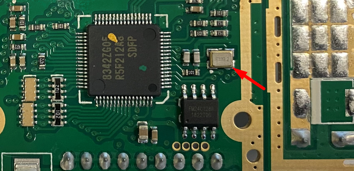
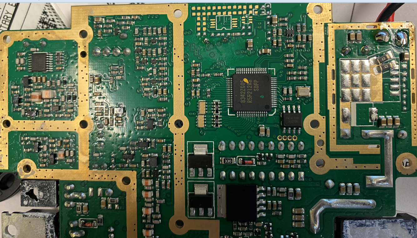
The pictures below show the 19.2 MHz crystal that was in question.

I've also included the block diagram, which confirms the NB circuit I sent earlier was from the SR-94HPC.

As mentioned before, the schematic is not our intellectual property, and we can't share what we do not own.

SdCT5xHorQ2S4elkUG0CcPZv6


FIGPZaAF1U65xoNULaZpysAVu
 

Attachments

  • Block Diagram - Copy.pdf
    415.5 KB · Views: 44
The pictures below show the 19.2 MHz crystal that was in question.

I've also included the block diagram, which confirms the NB circuit I sent earlier was from the SR-94HPC.

As mentioned before, the schematic is not our intellectual property, and we can't share what we do not own.

SdCT5xHorQ2S4elkUG0CcPZv6


FIGPZaAF1U65xoNULaZpysAVu

Hello Shawn,

I’ve only had a little time to work on this project so far today. The schematic clip that was sent several days ago, was only identified as the MCU line. Until today I was unaware the radio had a pair of MCU’s. When I confirmed the first MCU was not clocked at 19.2 but at 16.0 and could not find any 19.2, that did not appear to match the schematic. I am happy to report the SR-94HPC does have the 19.2 crystal and using loose coupling, I can actually hear it in the receiver on the bench HF rig. I’ll admit one other error I made. The first CPU is not clocked at 16.0. That was the first harmonic of the true clock frequency at 8.0 Mhz.

What does that prove and how does it impact the completely inoperative NB function? Well, it does prove that Stryker’s schematic clip matches the block diagram I was sent today. For incorrectly suggesting another possibility, I sincerely apologize. However, Stryker has still done nothing to address the fundamental issue of how it’s possible to have ZERO noise blanker function, attached to a button that activates a previously undisclosed and otherwise hidden, ANL circuit?

Your engineer invested a good deal of time to use pictures, schematic clips and block diagrams to confirm the 19.2 clock but, never even tried to move over to the IF block, just to the left in your photo. Why was your engineer not compelled to address the NB issue by placing a red arrow at Q6 (Noise blanker output transistor), like he did for X1? Could it be because we are not going to find effective blanking pulses? In place of the NB schematic which I assumed well in advance, would not be shared, why not simply take the option to outline any test situation that can demonstrate any ability to generate blanking action, with any type of impulse interference?

After years of suffering with no noise blanker, I assure you that there has NEVER been a situation where I could get this radio to trigger noise blanking. Furthermore, it has been frustrating to have to deal with the distortion of an unwanted ANL, that has not been set up to function independently, from the malfunctioning NB.

To summarize, the issue is that your noise blanker doesn’t work under any circumstances and it was replaced with an undisclosed ANL, that works exactly as it should. Poorly! Now, is Stryker willing to address their mistakes (as I did), by confirming ZERO NB function and fix it or, are you going to update your advertising to reflect the fact that NB has been replaced with ANL? Either one of these remedies, is the only honest way to resolve your NB problem.

Regards,
Donald.
 
I haven't heard back from Stryker today so I sent Shawn the following email:

Hello Shawn,

In a previous email you stated “I will also send you the location of the components”. The part I am having the most trouble locating is Q6, the noise blanker output. With one red arrow pointing to that part on the PC board, I can easily diagnose Stryker’s NB problem in the SR-94HPC. We should be seeing positive pulses on the base, that coincide with impulse noise, while the collector has an inverted output that is providing shunt pulses to ground, at the input of the IF filter. This activity should only cease, when the NB is switched off. At which point, the impulse noise should become apparent at the collector of Q6.

Just knowing where Q6 is will allow me to confirm many things. First, that the schematic matches what is coming off the assembly line. More importantly, it gives me the ability to spot the issue that has inhibited NB function in every SR-94HPC sold so far. I’ll be able to tell if the circuit has a low impedance path from the collector of Q6, back to the input of the IF filter. I can confirm if and when the broadband input RF circuit tries to trigger, by looking at the base. I can determine if the base drive is providing enough current to produce the anticipated blanking pulses at the collector.

Last but not least, Stryker can end the practice of secretly installing ANL and actually begin to provide the advertised function of Noise Blanking. Of course, at that point your engineer should reprogram the software so that owners can independently select from a working NB or, NB and ANL combined. That’s simply common practice for any rig having both filters, as opposed to just on or off for both like the software is programed now. Please be as eager to point out the location of Q6, as you were to point out X1, so that we can finally fix this problem that has plagued buyers for years.

Best regards,
Donald.
 
Today is the second day of "crickets" from Stryker and that has prompted the following email to the company:

Hello Shawn,

After nearly a week of trying to address this malfunctioning NB circuit, Stryker has still failed to provide any evidence that the NB circuit in the schematic, has been installed on the PC board and has refused to outline any test procedure used to confirm NB function, prior to selling thousands of defective radios. They have also been all falsely advertised with no mention of a less effective and secretly installed ANL circuit, being used in place of a much more effective NB circuit. Stryker is the ONLY company selling a radio with ANL, that excludes ALL mention of that feature in advertising and on the radio itself, while activating it with a button mislabeled as NB only… WHY??? Understand at this point it doesn’t even matter if Stryker claims they haven’t intentionally deceived or taken advantage of anyone because, Stryker has deceived all SR-94HPC buyers that were taken advantage of with working ANL ONLY, including myself.

Ignoring this deceptive substitute for years, has not made the problem go away. Continuing to expect that it will, is insanity. If Stryker continues to ignore this issue for the remainder of the week, we will easily assume the company has been well aware of the false advertising and is comfortable with it. For now… The basic question remains. Where is Q6 and how did Stryker ever confirm its functionality, prior to manufacturing thousands of defective radios that just happen to have false labeling on their ANL switch, to help hide this NB deception?

Regards,
Donald.
 

dxChat
Help Users
  • No one is chatting at the moment.
  • @ Wildcat27:
    Hello I have a old school 2950 receives great on all modes and transmits great on AM but no transmit on SSB. Does anyone have any idea?
  • @ ButtFuzz:
    Good evening from Sunny Salem! What’s shaking?
  • dxBot:
    63Sprint has left the room.
  • dxBot:
    kennyjames 0151 has left the room.