Hmmm...Where to begin...
Well, how about - Hi! Welcome to the forum!
")
Ahemn... - my postings tend to get backed up in emotion due to many memories of these repairs having a tie in with friends, the time and effort - or a combination of both - getting in the way of my thoughts.
Ok, with the intros behind, then also note that many of the said memories were from times I had to sink more money into a radio than it was worth. So the lessons I learned, from repairs to these - boy I'd hate to see others suffer from it...
My apologies also if I came across a little strong - again due to my own frustrations when doing repairs on these chassis - the in's out's and complexities these designers used and incorporated - worse than peeling onions and far more intricate...
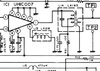
The above paragraph, Pin 10 - you didn't catch the meaning - Pin 10 is a Data select for a divisor, you know that, but if the Pin 18 was ever lifted, or L50 ever "popped" open and you did not know it - POOF - the LOGIC buffer to compare the input pins to the ROM - just got destroyed
- The "static pokes" and L50s' proximity to lift potentials from ground to another level - leaves the chip open for ripple effects - partly the reason for the use of L50 was to raise the PLL's noise level to a point where it can be properly filtered thru the use of the CCA (Chip Cap Array) along with Ground loop stuff like C60 and bypassing to lessen problems of latching glitches and nonesuch matters of noise from affecting the PLL's ability to track - so it can run at 8 volt margins and not have to worry about noise rising above a safe Operating Area of any of the pins.
- By your description of symtoms - the possibilities still exist for the PLL to have failed.
Why?
- IF ROM or Divisor Input was damaged - the chips own internal arrays will still try to work, but will not offer any latching or semblance of working because it is waiting for a logical event to occur,
- - that is; to fire a set of pins to ground thru the BCD switch and a safety latch to engage, telling the system ok, here's something off the menu - order up!
- Now, interestingly enough, if you took out that PLL chip, your "defaults" are just what you posted as far as external oscillator and varactor voltages - they'd be "preset" by the initial power-up sequence to oscillate at or above 36MHz and the Varactor is tickled to start "varacting" at a pre-set voltage that the PLL chip then "sinks" into itself (skipping pulses or adding pulses) to make the varactor start working the oscillator stages in the UHIC 007 and also at the Voice Lock Oscillator.
- Those conditions exist whether you have the PLL in or not.
- When it works, you'll have the defaults you'd see in the manual - your job is to align it to that.
So your board is healthy - I only hope the PLL is still able to function - but your Pin 6 LOCK function shows something different...
Note the "Dot" - that dot is supposed to help you identify pins - and if Pin 18 is your dot, you will get a chip with the "dot" in a different location - aka - Pin 1 - so you know - you'd be hard pressed to find a way to orient the chip and I've seen work that has them in backwards - YELP - that's the rub, they wanted ground - but reversed the chip to do it.
That's why I get mad at Uniden and those days of 'yore, because their standard ID was known, I just get frustrated when you have to argue finer points of Swiss Cheese and Cottage Cheese and their influences on the GOAT (not Greatest Of All Time) - more like the "scape" - to the customer that denies more things they've done to it. than Current Political Events can ever partake in...
Ok, last ditch effort, locate the "gating oscillator" a pair of gated inputs designed to run at two different speeds - they in turn "clock" against the Divisor and the Xtal - any error? They check for and then add / supplant a pulse or two to kick the Varactor up a notch to "slow down" or "skip" when they miss a count - forcing the Varactor to see a lower voltage and boost the VCO frequency.
- Why these two?
- You have two caps that run in this loop to separate and kick the pulse trains in and out of this loop section so if the caps are not up to snuff - they won't do their job and kick the Varactor and keep the loop working.
I just said earlier - that I worry it's PLL is DOA - but that's my opinion.
If you can get this fixed and working, you've proven me wrong, which is FANTASTIC! considering the outcome - it's something you really would want to have - all of us are behind you on this...