This is crude, but you should get the idea.
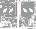
Power for the rear board travels through the small wire from the fuse holders, touching the protection diode, and then to the rear trace on the board. From there it goes through the wire with the chokes to the trace where the output transformer is soldered. Power then flows through the transformer to the other side where it is soldered to the traces that the collectors are soldered to. That is where the transistors get there power.
The blue circle is the diode, the green is the chokes, and red is the path of power.