• You can now help support WorldwideDX when you shop on Amazon at no additional cost to you! Simply follow this Shop on Amazon link first and a portion of any purchase is sent to WorldwideDX to help with site costs.

Texas Star Amplifier problems

Long night,

not a problem, i completely understand how something can read more complicated than it actually is.

so, the old diode was just a button with no leads on it.

the bottom of that old diode was soldered to the board.
that is ground.
so, the NON-banded end of your new diode (anode) gets soldered to that same spot.

the top of your old diode had a wire soldered to it. that wire had one end soldered to the fuses, and the other end soldered to that trace that is directly behind the spot where the old diode was. this wire was bent down so that the middle of it could be soldered to the top of the old diode.

looks like this:

View attachment 58421

so now you have your new diode with the NON-banded end soldered to that ground trace (where the diagram above says "D3").

the next step is to bend the other lead (banded end) over towards the back of the amp and solder it to that trace in the diagram that is directly to the right of the ground trace.

at this point you will have a diode with one end soldered to the ground trace (where the D3 label is in the diagram above), and the other end soldered to that trace that is just to the right of it (in the diagram above).

the last step is to get a short length of wire (12ga. or bigger, don't use thin wire) and solder one end to the top lead of your new diode (the end that goes to that trace on the right). the other end of this wire gets soldered to the fuse holder.

i know that we don't yet know which end of your new diode is the "banded end (cathode) and which end is the NON-banded end (anode).

the way we will figure this out is with our digital multimeter set to diode test function (probably has a diode symbol on that switch position).

take your positive (red) lead and touch it to one end of the new diode.
take your negative (black) lead and touch it to the other end of the new diode.

now look at the display on the meter. if it reads a voltage like somewhere around .6 volts (.583 for example) then your black lead is connected to the cathode (banded end) of the diode. put a mark or a line on this end of the diode.

if your meter doesn't read anything, then switch the leads around and re-read the paragraph above.

hope this helps.
LC
Hi loose cannon. Your explination and instructions are very clear and most helpful to me with my limited knowledge. Don't know how to thank you for your help! I will be sure to let you know how this comes out when I get the new replacement diode.
Chuck Saylor
 
not a problem im happy to help.

please do come back to the thread with your results as it helps future forum members find answers.

we tend to have a lot of threads where people never let us know if the item ever got fixed or not.

good luck!
LC
 
Long night,

not a problem, i completely understand how something can read more complicated than it actually is.

so, the old diode was just a button with no leads on it.

the bottom of that old diode was soldered to the board.
that is ground.
so, the NON-banded end of your new diode (anode) gets soldered to that same spot.

the top of your old diode had a wire soldered to it. that wire had one end soldered to the fuses, and the other end soldered to that trace that is directly behind the spot where the old diode was. this wire was bent down so that the middle of it could be soldered to the top of the old diode.

looks like this:

View attachment 58421

so now you have your new diode with the NON-banded end soldered to that ground trace (where the diagram above says "D3").

the next step is to bend the other lead (banded end) over towards the back of the amp and solder it to that trace in the diagram that is directly to the right of the ground trace.

at this point you will have a diode with one end soldered to the ground trace (where the D3 label is in the diagram above), and the other end soldered to that trace that is just to the right of it (in the diagram above).

the last step is to get a short length of wire (12ga. or bigger, don't use thin wire) and solder one end to the top lead of your new diode (the end that goes to that trace on the right). the other end of this wire gets soldered to the fuse holder.

i know that we don't yet know which end of your new diode is the "banded end (cathode) and which end is the NON-banded end (anode).

the way we will figure this out is with our digital multimeter set to diode test function (probably has a diode symbol on that switch position).

take your positive (red) lead and touch it to one end of the new diode.
take your negative (black) lead and touch it to the other end of the new diode.

now look at the display on the meter. if it reads a voltage like somewhere around .6 volts (.583 for example) then your black lead is connected to the cathode (banded end) of the diode. put a mark or a line on this end of the diode.

if your meter doesn't read anything, then switch the leads around and re-read the paragraph above.

hope this helps.
LC
Hi loose cannon. You are very helpful and patient with me. I will follow your instructions and let you know how I come out. I will also get a new keying transistor just in case.
Thank you for all your help here
Chuck Saylor
 
  • Like
Reactions: loosecannon
Long night,

not a problem, i completely understand how something can read more complicated than it actually is.

so, the old diode was just a button with no leads on it.

the bottom of that old diode was soldered to the board.
that is ground.
so, the NON-banded end of your new diode (anode) gets soldered to that same spot.

the top of your old diode had a wire soldered to it. that wire had one end soldered to the fuses, and the other end soldered to that trace that is directly behind the spot where the old diode was. this wire was bent down so that the middle of it could be soldered to the top of the old diode.

looks like this:

View attachment 58421

so now you have your new diode with the NON-banded end soldered to that ground trace (where the diagram above says "D3").

the next step is to bend the other lead (banded end) over towards the back of the amp and solder it to that trace in the diagram that is directly to the right of the ground trace.

at this point you will have a diode with one end soldered to the ground trace (where the D3 label is in the diagram above), and the other end soldered to that trace that is just to the right of it (in the diagram above).

the last step is to get a short length of wire (12ga. or bigger, don't use thin wire) and solder one end to the top lead of your new diode (the end that goes to that trace on the right). the other end of this wire gets soldered to the fuse holder.

i know that we don't yet know which end of your new diode is the "banded end (cathode) and which end is the NON-banded end (anode).

the way we will figure this out is with our digital multimeter set to diode test function (probably has a diode symbol on that switch position).

take your positive (red) lead and touch it to one end of the new diode.
take your negative (black) lead and touch it to the other end of the new diode.

now look at the display on the meter. if it reads a voltage like somewhere around .6 volts (.583 for example) then your black lead is connected to the cathode (banded end) of the diode. put a mark or a line on this end of the diode.

if your meter doesn't read anything, then switch the leads around and re-read the paragraph above.

hope this helps.
LC
Hi loose cannon. I have my new reverse polarity diode and am ready to put it in. It is a button type with no marking to tell me which end is anode and which is cathode and looks the same on both ends. Can you tell me how to find which end is which?
Thanks Chuck
 
  • Like
Reactions: NZ8N
Long night,

not a problem, i completely understand how something can read more complicated than it actually is.

so, the old diode was just a button with no leads on it.

the bottom of that old diode was soldered to the board.
that is ground.
so, the NON-banded end of your new diode (anode) gets soldered to that same spot.

the top of your old diode had a wire soldered to it. that wire had one end soldered to the fuses, and the other end soldered to that trace that is directly behind the spot where the old diode was. this wire was bent down so that the middle of it could be soldered to the top of the old diode.

looks like this:

View attachment 58421

so now you have your new diode with the NON-banded end soldered to that ground trace (where the diagram above says "D3").

the next step is to bend the other lead (banded end) over towards the back of the amp and solder it to that trace in the diagram that is directly to the right of the ground trace.

at this point you will have a diode with one end soldered to the ground trace (where the D3 label is in the diagram above), and the other end soldered to that trace that is just to the right of it (in the diagram above).

the last step is to get a short length of wire (12ga. or bigger, don't use thin wire) and solder one end to the top lead of your new diode (the end that goes to that trace on the right). the other end of this wire gets soldered to the fuse holder.

i know that we don't yet know which end of your new diode is the "banded end (cathode) and which end is the NON-banded end (anode).

the way we will figure this out is with our digital multimeter set to diode test function (probably has a diode symbol on that switch position).

take your positive (red) lead and touch it to one end of the new diode.
take your negative (black) lead and touch it to the other end of the new diode.

now look at the display on the meter. if it reads a voltage like somewhere around .6 volts (.583 for example) then your black lead is connected to the cathode (banded end) of the diode. put a mark or a line on this end of the diode.

if your meter doesn't read anything, then switch the leads around and re-read the paragraph above.

hope this helps.
LC
Hi loose cannon. I was able to get the texas star 500 dx up and running. The only part that I needed to replace was the reverse polarity diode. Wanted to thank you for all your help and patience Sir.
 
awesome!!!

glad to hear that's all it was.

be sure to use two 35 amp fuses in those fuse holders.
if they blow because the amp draws more current than that on modulation peaks then you can go up to 40 amp fuses.
LC
 
awesome!!!

glad to hear that's all it was.

be sure to use two 35 amp fuses in those fuse holders.
if they blow because the amp draws more current than that on modulation peaks then you can go up to 40 amp fuses.
LC
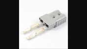
Personally I would ditch those fuse holders and upgrade to 8ga wire to each board for both positive and negative combining into an anderson connector, and put the fuse as close to the supply as possible.
I don't have factory fuse holders in any of my TS amps anymore.
I ditched the ones from my 667 25 years ago and my Sweet Sixteen never came with them.
They are just too prone to failure and upgrading the power wire both keeps the power wire cooler and helps the amp do what it's capable of doing. I gained 150 watts on my 667 when I upped the power wire. It's a very worth while upgrade.

Like this.
1650513607267.png
 
Personally I would ditch those fuse holders and upgrade to 8ga wire to each board for both positive and negative combining into an anderson connector, and put the fuse as close to the supply as possible.
I don't have factory fuse holders in any of my TS amps anymore.
I ditched the ones from my 667 25 years ago and my Sweet Sixteen never came with them.
They are just too prone to failure and upgrading the power wire both keeps the power wire cooler and helps the amp do what it's capable of doing. I gained 150 watts on my 667 when I upped the power wire. It's a very worth while upgrade.

Like this.
View attachment 58517
Thank for the great information on this. Will do!!!
 
Personally I would ditch those fuse holders and upgrade to 8ga wire to each board for both positive and negative combining into an anderson connector, and put the fuse as close to the supply as possible.
I don't have factory fuse holders in any of my TS amps anymore.
I ditched the ones from my 667 25 years ago and my Sweet Sixteen never came with them.
They are just too prone to failure and upgrading the power wire both keeps the power wire cooler and helps the amp do what it's capable of doing. I gained 150 watts on my 667 when I upped the power wire. It's a very worth while upgrade.

Like this.
View attachment 58517
Agree the stock fuse holders are failure prone , I have seen them get hot and fail on both the 500 and 667.

73
Jeff
 
I do the power wire upgrades as well.

just make sure you have the right soldering tools for soldering to large gauge wire, and the fabrication skills to enlarge the holes so you can put proper strain relief on the new wires.

also don't forget to put a fuse in line near the amp, and as with any wiring that goes straight to the battery, a fuse right at the battery for fire protection.
LC
 
  • Like
Reactions: Shadetree Mechanic

dxChat
Help Users
  • No one is chatting at the moment.