• You can now help support WorldwideDX when you shop on Amazon at no additional cost to you! Simply follow this Shop on Amazon link first and a portion of any purchase is sent to WorldwideDX to help with site costs.

Texas Star Amplifier problems

long night

Active Member
Jan 8, 2020
202
39
38
75
My texas star 500 amplifier quit working. No lights for power or meter. I was told the power transistors were probably the issue and needed to be replaced. I also noticed one of the fuse holders was bad and replaced it. I then replaced all four power transistors and some resistors that looked bad. I attached it to the power supply, but still no power or meter lights. I also now see that the voltage meter on the power supply goes to zero when the amp is connected. Not certain what the issue is? Anyone have any ideas one what the problem might be? A picture of the wiring in the input area of the amp would be helpful.

Thanks for any help.
 

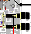
not sure of the age of your amp, but there is usually a diode that looks like this:


here is a pic of it:
1649546818303.png

if this diode were shorted, you would have the symptoms you have now.

get your digital multimeter out and set it to diode check, then put the leads on the traces shown. one on the positive lead and one on the negative side.

you should see a voltage of around .6 volts with the leads oriented one way, and an open connection when you switch the leads around.

if it shows up as a shorted connection, you have found your problem.
LC
 
not sure of the age of your amp, but there is usually a diode that looks like this:


here is a pic of it:
View attachment 58328

if this diode were shorted, you would have the symptoms you have now.

get your digital multimeter out and set it to diode check, then put the leads on the traces shown. one on the positive lead and one on the negative side.

you should see a voltage of around .6 volts with the leads oriented one way, and an open connection when you switch the leads around.

if it shows up as a shorted connection, you have found your problem.
LC
So if D3 is shorted that may be the issue? Thanks loose cannon.
 
  • Like
Reactions: loosecannon
When you say you replaced all four power transistors if your talking about the Toshiba 2879 finals hang on the them. There is a good possibility that this was not the problem so these very expensive finals are probably still good.
 
  • Like
Reactions: Holydvr
So if D3 is shorted that may be the issue? Thanks loose cannon.
Hi loose cannon. I have ordered a new MR750 diode to replace the shorted out one in my texas star 500. The new one does not look like the old one which is a button type. Will that matter? Also I can see no stripe on the new one to determine current direction flow. Can you help me figure tat out?

Thank you.
 
sure thing, but let's do a couple of tests to make sure you have found your problem.

first a question, did you test the diode that was removed and confirm that it was indeed shorted?
you have to remove at least one side of the diode from the circuit in order to test it.

next, if you did test and remove the old diode, you should set your multimeter to read continuity and confirm that there is no connection from the positive side (you can measure this at the fuse holders) to ground. (the big wide trace the bottom of the old diode was soldered to)

we want to make sure that the diode was the culprit and not a symptom of another problem.

so check these items before installing your new diode.

when installing your new diode, you want the cathode (banded end) connected to the positive side, and the anode connected to ground.

this way, the diode won't conduct when power is connected properly.
if the power is connected backwards, the diode will conduct and blow the fuses.
this is one reason not to just put way over sized fuses in there, as they won't blow before more damage is done to the amp.

so, to determine which end of the diode is the cathode (banded) and which is the anode, set your multimeter to diode test function, and put the positive lead on one side of the diode and the negative lead on the other.

look at the meter and see if you read a "0" or open connection, or if you see a small voltage, like around .6 of a volt.

if you see the .6 of a volt then you know you have your positive lead on the anode and the negative lead on the cathode (banded end).

if you see the "0", then it is the opposite.

hope this helps.
LC
 
I also now see that the voltage meter on the power supply goes to zero when the amp is connected.
This is how the power supply protects itself from a short circuit.

It only takes one tiny solder bridge, shorting across a thin gap to cause this kind of short circuit. Any time those RF transistors get replaced, this is possible.

A bright light and a magnifier are a big help finding one of those.

The end of a protection diode with the band goes to the positive power supply. The end of the diode with no band goes to ground.

73
 
  • Like
Reactions: loosecannon
sure thing, but let's do a couple of tests to make sure you have found your problem.

first a question, did you test the diode that was removed and confirm that it was indeed shorted?
you have to remove at least one side of the diode from the circuit in order to test it.

next, if you did test and remove the old diode, you should set your multimeter to read continuity and confirm that there is no connection from the positive side (you can measure this at the fuse holders) to ground. (the big wide trace the bottom of the old diode was soldered to)

we want to make sure that the diode was the culprit and not a symptom of another problem.

so check these items before installing your new diode.

when installing your new diode, you want the cathode (banded end) connected to the positive side, and the anode connected to ground.

this way, the diode won't conduct when power is connected properly.
if the power is connected backwards, the diode will conduct and blow the fuses.
this is one reason not to just put way over sized fuses in there, as they won't blow before more damage is done to the amp.

so, to determine which end of the diode is the cathode (banded) and which is the anode, set your multimeter to diode test function, and put the positive lead on one side of the diode and the negative lead on the other.

look at the meter and see if you read a "0" or open connection, or if you see a small voltage, like around .6 of a volt.

if you see the .6 of a volt then you know you have your positive lead on the anode and the negative lead on the cathode (banded end).

if you see the "0", then it is the opposite.

hope this helps.
LC
Hi loose cannon. I have already removed the old diode. It is a button type reverse polarity diode. The top was soldered to the trace on the board and the bottom was sitting on a spot that looked like it was made for the diode to sit on. Not familiar with this type of dsiode and it has no band. If you can direct me as how to test it I would appreciate that very much. I assume you would touch one probe to the top of this diode and the other probe to the bottom to test it. Then reverse probes and test again with both tests having multimeter set on diode function. Please correct me if I am in error here. What should the tests show? Also is the bottom of this diode attached to the board in some faction or does it just sit on the board?
Thank you for your help here.
Sorry to seem a bit confused, but this is new to me and I am a little confused. Since the old diode is a button type with no stripe can I just replace it with a new diode positioned just the same. With the small end of the button soldered to the positive lead and board just as the old one was. The larger bottom end that just sat on the board, should it be attached in some way? I don't believe it was or could be soldered in place, but I may be wrong.
Thanks
 
I did a quick search for the MR750 diode and it looks like the banded end would be down according to the writing on the diode.
 
Long night,

not a problem, i completely understand how something can read more complicated than it actually is.

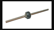
so, the old diode was just a button with no leads on it.

the bottom of that old diode was soldered to the board.
that is ground.
so, the NON-banded end of your new diode (anode) gets soldered to that same spot.

the top of your old diode had a wire soldered to it. that wire had one end soldered to the fuses, and the other end soldered to that trace that is directly behind the spot where the old diode was. this wire was bent down so that the middle of it could be soldered to the top of the old diode.

looks like this:
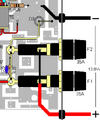
1649985069873.png

so now you have your new diode with the NON-banded end soldered to that ground trace (where the diagram above says "D3").

the next step is to bend the other lead (banded end) over towards the back of the amp and solder it to that trace in the diagram that is directly to the right of the ground trace.

at this point you will have a diode with one end soldered to the ground trace (where the D3 label is in the diagram above), and the other end soldered to that trace that is just to the right of it (in the diagram above).

the last step is to get a short length of wire (12ga. or bigger, don't use thin wire) and solder one end to the top lead of your new diode (the end that goes to that trace on the right). the other end of this wire gets soldered to the fuse holder.

i know that we don't yet know which end of your new diode is the "banded end (cathode) and which end is the NON-banded end (anode).

the way we will figure this out is with our digital multimeter set to diode test function (probably has a diode symbol on that switch position).

take your positive (red) lead and touch it to one end of the new diode.
take your negative (black) lead and touch it to the other end of the new diode.

now look at the display on the meter. if it reads a voltage like somewhere around .6 volts (.583 for example) then your black lead is connected to the cathode (banded end) of the diode. put a mark or a line on this end of the diode.

if your meter doesn't read anything, then switch the leads around and re-read the paragraph above.

hope this helps.
LC
 
These button type reverse polarity diodes have no bands on them.
Ok like I said I did a search for the part number listed in the schematic.... MR750... and found some marked with a band. Every one of them have the same polarity with the band under the words like this.
1649988600871.png
 

dxChat
Help Users
  • No one is chatting at the moment.