• You can now help support WorldwideDX when you shop on Amazon at no additional cost to you! Simply follow this Shop on Amazon link first and a portion of any purchase is sent to WorldwideDX to help with site costs.
  • A Winner has been selected for the 2025 Radioddity Cyber Monday giveaway! Click Here to see who won!

Texas star dx-350 hdv repair (toasted)

Eldorado828

828 in the Lonestar state (WDX-828)
I Support WorldwideDX.com!
Feb 21, 2016
4,763
9,453
523
The Panhandle of Texas
Hello wwdx friends, I haven't been very hobby motivated lately so I bought a cooked 350 hdv as a project to stimulate my brain and reel me back in. I like this sort of thing so it should be a beneficial learning experience. I've been studying the schemo and layout along with the parts list I've found here on wwdx and from post that some of you have contributed to. What a great forum!

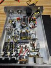
I bought the amp knowing that it does not work and all the seller could tell me is that he was told that it does not transmit. It's currently heading towards me but I have a few pictures from the seller that lead me to believe that the pills are cooked to start with.

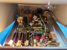
I'll use this thread to update but I'm no guru so I'll more than likely be reaching out the wwdx knowledge as I move along. I've repaired, modded many radios but never a full on repair of an amp so here we go.
Screenshot_20250529_194656_eBay.jpgScreenshot_20250529_194700_eBay.jpg
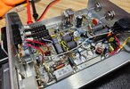
Right away I see r5 and r7 cooked so I'll go ahead and assume the pills are more than likely toast. I've got a matched set of hg2879 that I had stashed away and this just might be their calling.

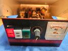
I have an idea where I'll start the diagnosis but I'm all ears for suggestions.
 

If I was doing this repair.....these are parts I would automatically replace.....
Of course along with the two power transistors, Q3 & Q4 .....
1) .... R5 , R7 , R8 , C10 & C12 ..... If not there, install C11 & C13 ......
2) .... Check for correct value C9 , C14 , C19 , R6 & R9
@Ranch55 thank you sir and I will heed to your advice. I will post my findings, results and probably be asking lots of questions.
 
If I was doing this repair.....these are parts I would automatically replace.....
Of course along with the two power transistors, Q3 & Q4 .....
1) .... R5 , R7 , R8 , C10 & C12 ..... If not there, install C11 & C13 ......
2) .... Check for correct value C9 , C14 , C19 , R6 & R9
So i notice that on the newer Texas star amps with dei pills, they no longer install c11 and c13 when they're built new. What is the purpose for those caps and why are they no longer installed from newest versions?
 
Update 1

Received the amp Monday and it is in immaculate physical condition, i would have thought it was new so that's a plus.

Now once inside the preliminary is what I expected with the pills being shot.

Now it gets interesting after removing the obvious failed parts. Someone has been in there but had only attempted to swap a couple parts.

R6 and R7 are toast and not the correct value either. Instead of 10 ohm they were 15 ohm....
R8 was the most obvious as they had simply cut the leeds and attached another incorrect value in its place. Instead of being a 1.6 ohm half watt, it had been replaced with a 1.1 1/4 watt...

The rest of it including the pills was all original as the soldering told the story.

I tested all the other resistors, caps, diodes on the board to see if they are within the correct values and all else falls within spec.

So during the resistor checks I found the Texas star schematic and parts list to be incorrect on so far just one value. The Texas star parts list shows R11 to be 1.5k ohms but it is incorrect, it's supposed to be 15k ohms so that needs to be corrected here on the wwdx page. It had me stumped as to why when I was testing it the tolerance was so far off but it was actually right within spec and the parts list was incorrect.

Anyway, I had everything in parts except for the one 1.6 ohm 1/2 watt for R8, go figure.... so now I'm waiting for it to hit my mailbox before I can finish or get it running again.

Here she be, in pieces to inspect the underside of the board and for a good cleaning because the original TS builders don't skimp with the flux!
20250603_172150.jpg20250603_171803.jpg20250603_171746.jpg
More to come!
 
Ok gents, I checked tons of parts and swapped out the ones that were not within tolerance. Lots of cleaning and finally got it all put back together this evening with a fresh pair of Hg pills.

So now I'm going through to check bias and I'm stumped a little bit. According to Texas star, from the base of the transistors to ground I should have about 1.3 ohms and I'm seeing around 1.5 on my meter. The 2 10 ohms are 1% tolerance and the 1.6 is a 5%.

Now the second part is while manually keying the amp with no rf, from the base to ground I should get .61 or .62 volts but I'm seeing about .66 or .67 volts.

So I realize that my bias voltage is a tad high.

Comments, suggestions? Your help is appreciated.
 

Attachments

  • 20250608_205115.jpg
    20250608_205115.jpg
    1.9 MB · Views: 144
  • 20250608_205200.jpg
    20250608_205200.jpg
    2.1 MB · Views: 149
  • Like
Reactions: Shadetree Mechanic
What really matters is the current the transistors draw. Each pair has a 25-ohm 5-Watt resistor as the base-bias current source. Unsolder one end of each of these resistors. Put a current meter in line with the positive power supply wire. Use a gator-clip lead grounded at one end, and touch the other end to the NON banded end of the black diode just to the rear of the relay. This will key it. Read the current and you'll see what current the relay and the lights alone are drawing. This is now your reference current, the equivalent of zero transistor current. Now hook one of the bias-source resistors back. Key it again with the gator lead and read the current drain. Subtract your reference reading and this is the zero-signal bias current for that pair of transistors. Should be under a quarter of an Amp (250 mA). Now connect the bias resistor on the other pair. Key it. This reading minus the previous one is the idle current for the second pair of RF transistors.

Texas Star chose not to provide an easy hookup to measure idle current. This is the method we use.

73
 
Ok gents, I checked tons of parts and swapped out the ones that were not within tolerance. Lots of cleaning and finally got it all put back together this evening with a fresh pair of Hg pills.

So now I'm going through to check bias and I'm stumped a little bit. According to Texas star, from the base of the transistors to ground I should have about 1.3 ohms and I'm seeing around 1.5 on my meter. The 2 10 ohms are 1% tolerance and the 1.6 is a 5%.

Now the second part is while manually keying the amp with no rf, from the base to ground I should get .61 or .62 volts but I'm seeing about .66 or .67 volts.

So I realize that my bias voltage is a tad high.

Comments, suggestions? Your help is appreciated.
I would say you are okay with those measurements.......
I have seen the same variations using Toshiba's and you will see variations using the HG's.......
Key the amplifier up with a 2 watt am drive input .......
 
Only 1 pair of transistors in this amplifier.....
Yes sir, it's a 350 hdv so a pair 2879's.
I would say you are okay with those measurements.......
I have seen the same variations using Toshiba's and you will see variations using the HG's.......
Key the amplifier up with a 2 watt am drive input .......
I've been thinking about it throughout the day and I didn't consider the voltage i have the power supply at. I was a little tired by the time I finished last night.

I'll see where my supply voltage is set at this evening and play with it some to see how it affects my amp readings and report back.
 
Well gentlemen, I thank you all very much for your expertise. You guys are some good people, you can't not love the world of wwdx!

I had the supply voltage set at 14.8 so I brought it down to 14.2 and all my bias readings went down even closer to what Texas star suggests.

I put rf into it this evening and it is working really well. Pass through tune is flat, input tune is pretty flat, pre-amp works (not like I'll ever use it), the dial-a-watt works like it's supposed to(won't use it either) and the ssb delay and output is on target too. Not bad for a toasted 100 dollar cosmetically mint amplifier and I thank you all for helping me out
Here she be
 

Attachments

  • 20250609_203713.jpg
    20250609_203713.jpg
    2 MB · Views: 130
  • 20250609_203730.jpg
    20250609_203730.jpg
    2.1 MB · Views: 135
Well gentlemen, I'm back on this one again. It was working really well with no issues and then I keyed up on ssb and as soon as the relay clicked it popped the fuse. No smoke, no nothing, just a click and it was over. The covers off now and a quick preliminary gives me no clue. Nothing looks smoked, checking bias it still looks good so I'm going to have to do a little research.
Go figure.....

As a side note, as soon as I install a new fuse and even with the power button off the fuse immediately pops while the meter needle slightly moves..

I'm open to hints.
 

dxChat
Help Users
  • No one is chatting at the moment.