• You can now help support WorldwideDX when you shop on Amazon at no additional cost to you! Simply follow this Shop on Amazon link first and a portion of any purchase is sent to WorldwideDX to help with site costs.

Texas Star DX500 repair advice

Matego

New Member
May 17, 2019
7
1
3
44
First off, thanks for the great site and info you guys share. I am very much a novice to the CB world. I am a diesel mechanic and traded some work for an older DX500 amp that he said had a smoke smell from it last time he used it.
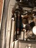
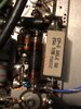
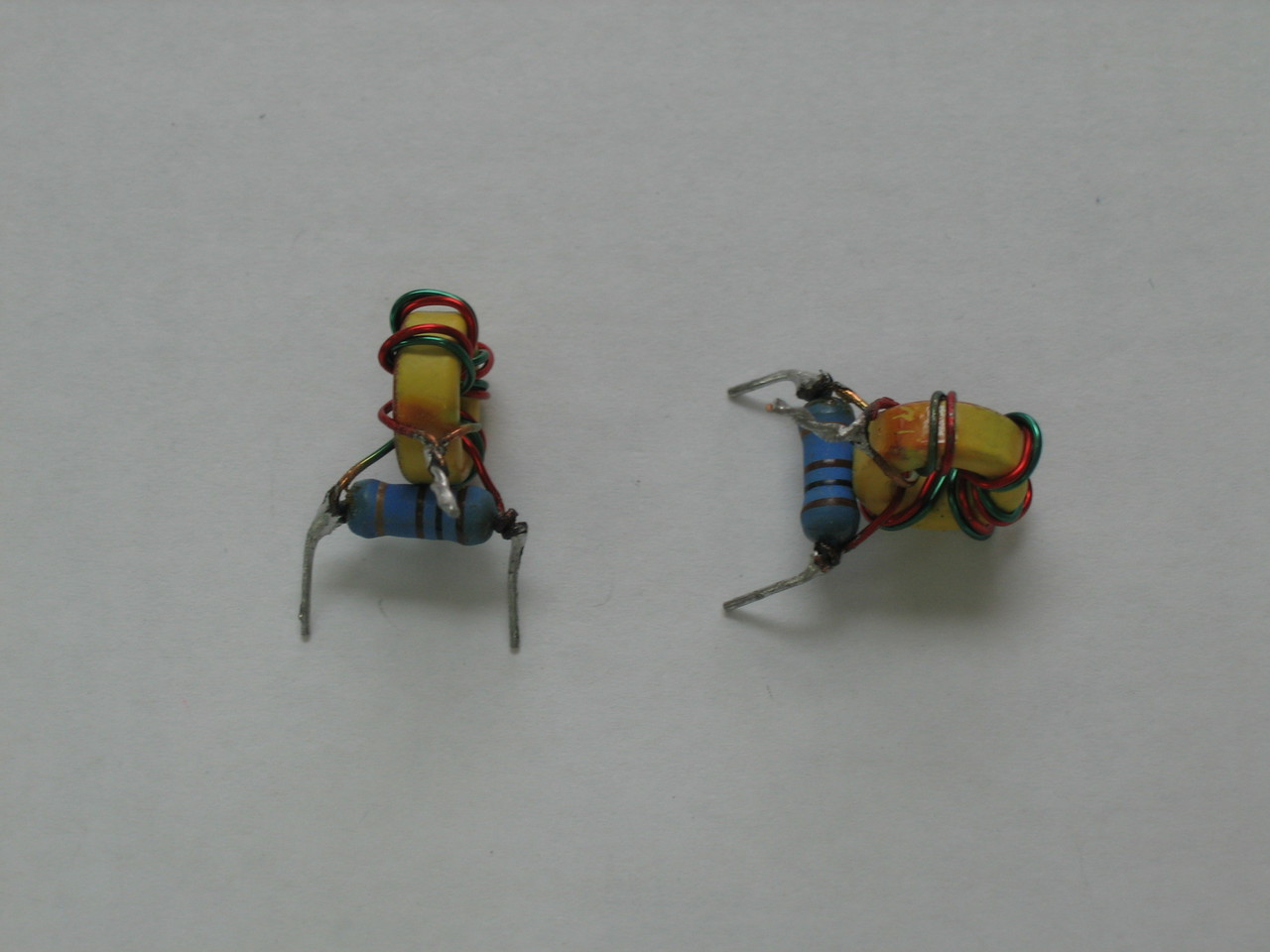
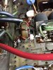
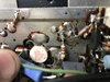
I pulled off the cover and the 10uf chokes are burned. I know he has a tuned up Connex radio and the power leads had spade connections on them. I am thinking he was over driving it and had a poor power feed dropping voltage. Those crimp on spades don’t carry current well.
Anyway, I was going to replace the chokes and the 25 ohm 5 watt resistors. Is there anything else to check? Visually nothing else is discolored but I know that’s not an accurate way to tell if there is more damage.
I do not know what I am going to do with this once completed. I do have a Bearcat 980 in my Jeep but I don’t have a need for something this big. I would like to get it working properly and stash away for a possible future project. Thanks for any help.
 

Attachments

  • 5CE3FAEA-B57A-41E6-B387-9298800E8C3F.jpeg
    5CE3FAEA-B57A-41E6-B387-9298800E8C3F.jpeg
    1.2 MB · Views: 254
  • E813CFA4-0BA3-460F-88AF-89823D67AB0F.jpeg
    E813CFA4-0BA3-460F-88AF-89823D67AB0F.jpeg
    1.1 MB · Views: 254

I agree with Tallman. Spade connectors and driving it with a hot radio says a lot about the install so who knows what swr was on top of the already disastrous conditions. Odds are pretty high that the pills and parts around them might be toast. Of course that's what I would start looking into
 
Can't patch the hole in the top of a piston after a valve gets stuck open.

I'd love to see someone (else) post a step-by-step video showing how to test those expensive RF power transistors.

If even one of them is bad, all four usually have to be replaced. It's important that all four of them match each other reasonably well. Even if only one of them is bad, you'll play the devil finding a single replacement that properly matches the other three 2SC2879 transistors.

That part was redesigned around 2006 to comply with toxic-material rules that took effect in europe. The redesigned part doesn't "play well" with the older version when you mix and match them. The 2006 revision is marked with a red dot to the right of the type number. But that one is also now discontinued. Just muddies the water, if you want to find a single part that matches three old ones, just as an example. If the guy really drove it hard, more than one RF transistor will be bad.

Four new parts that are a properly-matched set will be the only way to get a reliable repair if even only one of those parts is bad.

Pretty dern likely they are.

There are a couple of less-obvious parts that also get replaced when the RF transistors have failed. If the bias resistors that go from the 25-ohm 5-Watt part to ground don't get replaced, you could blow out one or both pairs of new transistors the first or second time you key it. There is a 10-ohm resistor soldered from each transistors's input terminal to ground. If any of them looks overheated, that indicates a toasted RF transistor.

73
 
Another indicator of bad transistors would be if the combiner is burned up. The splitter generally won't burn up unless it is being WAY overdriven, but with what you are showing us, it might be.
Look for the torroids with the resistors to see if they are scorched.

Regular_Toriod_Combiners_002__08998.1438798775.1280.1280.JPG
 
I'd love to see someone (else) post a step-by-step video showing how to test those expensive RF power transistors.
I'll see what I can do about a video.
Here is how I test them.
1. Isolate the base and the collector from the circuit board(Heat solder and lift tabs)
2. attach transistor tester. If you don't have one an ohm meter will work.
3. Test the base to emitter junction like checking a diode.
I personally have never seen a transistor fail in another fashion.
Check the scope traces of some brand new never used transistors in my photo album.
They show even on bad transistors Base to Collector is good.
Base to Emitter is what shows bad,

https://www.worldwidedx.com/gallery/albums/tallman.447/

This is the tester I use to test and match the gain of transistors.

s-l300.jpg
 
Last edited:
  • Like
Reactions: Shadetree Mechanic
I ordered the chokes and 25 ohm resistors. From what I can see, the 10 ohm resistors to ground “appear” to be in good shape. The toroids look good as well.
Once I solder in the chokes and resistors, is there a way I can test the unit to see if it’s functional? I have a FLIR camera I can watch for hot spots. Several Fluke DMM’s and a 4 channel oscilloscope.
The scope I would have no idea what I was doing when it comes to electronics. I am usually using it to check Hall effect switches and compare cam/crank synchronization.

Thanks again for all the great info here! Now I have to go the antenna section and ask some more newbie questions.
 

Attachments

  • E00B16D3-BD8A-4A77-8109-BE169B52FE0F.jpeg
    E00B16D3-BD8A-4A77-8109-BE169B52FE0F.jpeg
    1.3 MB · Views: 270
  • D6A42D19-7B03-422D-9832-57A90B220E42.jpeg
    D6A42D19-7B03-422D-9832-57A90B220E42.jpeg
    2.4 MB · Views: 279
The torroid looks discolored, but I suspect that is more from age than anything else. The resistor looks in good shape so I would agree that it's most likely fine.

This is from a guy that worked at Texas Star.
 
  • Like
Reactions: Ranch55
Be sure to have the amp connected to a test load of suitable wattage. Do not connect a radio at this time. Apply the power and watch the ammeter of the power supply. It should be near zero. (Note: There will be an in rush of current as all of the capacitors charge up). If it drawing more than1/2 amp it could be oscillating. Oscillation blows a lot of amplifiers and the repair techs just happily throw more transistors in it and the problem is still in the amp only to fail again in a short time.
If you suspect it is oscillating that is the time to put probes on it and do some poking around.

Here is how you lift the tabs on the RF transistors. You hook under the tab you wish to lift apply heat until the solder melts. Be sure you lift and not pry the tabs up. Keep your face away from the backside of those picks or use a magnifying light between your face and the picks. You could STAB your self in the face with those wicked looking picks. Do not use too much force while lifting the tabs.
The tabs can tear off from the transistor.
image_13802.jpg


https://www.harborfreight.com/6-piece-pick-set-93514.html
 
Last edited:
  • Like
Reactions: Shadetree Mechanic
The most-frequent failure in the 2SC2879 can usually be identified by unsoldering just the base (input) terminal of each transistor.

The diode test of a typical DMM should show very close to 0.6 on a good transistor. Much higher, or much lower and that one is no good.

And yes, taking the collector (output) side loose and testing all three legs of the part is definitely better.

The input splitter seen in the pic above almost never shows visible damage. The output combiner, just to the rear of the relay is where the telltale damage is usually visible.

73
 
  • Like
Reactions: Shadetree Mechanic
Not for nothing but every time I look at the schematic for one of these, the path DC bias has to take in order to avoid an extra dollar on a 3 pole relay, cracks me up! Look at the schematic in the second post. Follow the antenna jack through the choke, relay and power switch. Notice the red 12 volt line is present here. It goes trough the power switch and a long, unshielded circuit trace before making connection to the input combiner to provide DC bias and light the meter lamp.

Anyone else see a problem with providing a direct path from the output, through a choke and one RF bypass cap, back to the input just to provide DC bias switching? Apply a little too much drive, the choke gets hot. The enamel discolors and becomes conductive, destroying its ability to drop RF voltage across a high impedance path. The result is the amplifier oscillates until some parts let the smoke out and no longer works with the correct drive.

The entire bias circuit is deficient in that it's entirely based on a resistive divider that provides no voltage regulation, thermal tracking or headroom if you apply a bit too much voltage. Sometimes the little resistor opens up and applies all 12 volts to the transistor base. Then they had the nerve to introduce this likely feedback loop by using cheap parts to "Jerry rig" the bias switching, that are prone to failure.
 
  • Like
Reactions: Shadetree Mechanic
I soldered in the chokes and resistors. I put my ammeter in-line with the positive feed and turned it on. It was pulling .080 amps when turned on to AM and .115 amps when I hit the SSB button. My FLIR camera shows no hot spots. I had no radio hooked to it or an antenna.
I checked and there are no CB shops in Charleston S.C. I wanted to have someone hook it up and check the operation with the correct equipment. I am having high SWR problems (1.3 CH1, 2.4 CH40) with my Jeep, I don’t want to fry something testing it out.
 

dxChat
Help Users
  • No one is chatting at the moment.
  • @ Wildcat27:
    Hello I have a old school 2950 receives great on all modes and transmits great on AM but no transmit on SSB. Does anyone have any idea?
  • @ ButtFuzz:
    Good evening from Sunny Salem! What’s shaking?