• You can now help support WorldwideDX when you shop on Amazon at no additional cost to you! Simply follow this Shop on Amazon link first and a portion of any purchase is sent to WorldwideDX to help with site costs.

The Myth Surrounding Antenna Take Off Angles

Everyone talks about as if it was the most important thing to consider when attempting to work DX stations or local stations and as if it was a cast in stone property of antennas that any deviation from the specs will surely mean poor contacts. I have been saying for years to forget about trying to optimize your TOA and simply get your antenna up as high as you can and don't worry about what height is the best for working into a specific area of the world. I found this article on Eham written by Tom Rauch, W8JI, that sums things up nicely.


The Myth of Takeoff Angle

from Tom Rauch - W8JI on April 26, 2010
Website: www.w8ji.com
View comments about this article!

The Myth of Takeoff Angle

Antenna discussions and articles often emphasize take off angle. We commonly read or hear that a low takeoff angle is good for DX, and that a high takeoff angle is good for local or short-range work. This is exactly what a good friend of mine, the author of one of the most popular antenna modeling programs, often showed angst over. He often expressed great reservation in including TOA in his software, but felt he had to include take off angle because people expected it. In fact, if we go to the help menu in most versions of his software and search for instructions on using TOA (or takeoff angle), help is not there!
So what is takeoff angle? How can we use it? Is it useful for anything? My answer to that, surprisingly to the great believers in TOA, is TOA is not worth anything by itself. Let us look at some examples, and see how little value TOA really has.
Vertical vs. Dipole
We all know a vertical antenna is great for DX because it has a "low takeoff angle", and a modest height dipole is better for modest distances because it has a "high takeoff angle". Let us see how true this is.
image001.png

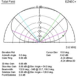
Figure 1: Dipole at 1/3 wavelength
This dipole is 1/3 wavelength high (figure 1). The peak gain is 6.66 dBi, and it has a takeoff angle of 54 degrees. At 15 degrees, dipole field intensity is .42 dBi. Few who focus on takeoff angle would consider this antenna "DX worthy", or even think it would make DX contacts.
image004.gif

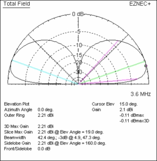
Figure 2: Vertical with 16 radials
We see now that a vertical with 16 radials (figure 2) has peak gain at 19 degrees, where gain is 2.21 dBi. Gain at 15 degrees, an angle considered very useful for long haul DX on lower HF bands, is 2.1 dBi. This vertical has only 1.7 dB more signal level than the useless cloud warmer dipole at the very useful low band DX angle of 15 degrees! At 19 degrees, the peak radiation angle of the vertical, the dipole and vertical are essentially equal in field strength even though the vertical has a TOA of 19 degrees and the dipole has a TOA of 54 degrees.
This does not mean the vertical is useless for closer contacts, but it certainly is at a huge disadvantage compared to the dipole. It also does not mean the dipole will not work DX, or will not at times be stronger than the vertical over very long distances. Small differences in location, propagation, and installation could easily make the dipole the better antenna for long distances. The only sure bet is the vertical will not be good for very high angle propagation.
Obviously, TOA by itself tells us little about an antenna's ability to be a good DX antenna. What then is important? With what should we really be concerned?
The answer is almost painfully logical; we want maximum available field strength over the entire useful range of angles and directions. Peaks and nulls outside of the desired range of angles and directions are of no concern when our goal is developing the maximum most consistent signal into a specific desired location. We should not care about or even bother discussing TOA; we only want maximum field strength in our target area!
Nulls, a Major Problem We Ignore

We know we want maximum signal over the useful and most desired angles and directions of radiation, but we should never confuse that with maximum peak gain in that area. Peak gain, by itself, is as useless and meaningless as TOA. Let's look at a few examples of high useless gain.
Let's assume we are in the center of the USA, and we want to work most of the USA with our multiband antenna. We all know a low band loop, operated up near the high end of HF, has considerable gain. That is a good thing, isn't it? After all, everyone wants a high gain antenna.
image006.gif

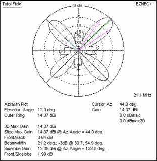
Figure 3: 80-meter loop on 15-meter band
Our eighty-meter full wave loop antenna (figure 3) has 14.37 dBi gain, about 6 dB more gain than a dipole, when used on fifteen meters. While this may sound attractive, this 6 dBd of additional field strength divides between four major lobes and four minor lobes. The average gain in the main lobes is 12.46 dBi or about 4 dB over a dipole. Worse yet, that gain is in an azimuth beamwidth of only 21 degrees for each of the lobes, and next to those peaks are holes or nulls up to 30 dB deep!
While we may have bragging rights of high isotropic referenced gain, our loop is very narrow area gain. Gain, at best, averages 4 dB over a dipole in four very specific peak directions of 44, 133, 224, and 315 degrees. The -4db points of the main lobes, at which point gain comes down to the peak gain of a dipole, is about 11 degrees.
It is statistically difficult to find contacts inside the main lobes, where the signal level would exceed a dipole!
image008.gif

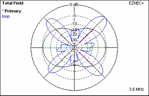
Figure 4: Loop and dipole superimposed
A comparison to simple dipole antenna (figure 4) shows the loop is better by as much as eight db in four very specific narrow directions. The total azimuth area where the loop is equal to or better than the dipole is 125 degrees. On the other hand, the dipole is better than the loop over 235 degrees of azimuth! When located almost anywhere in the mainland USA, we would have far better average signal levels in the USA with a small half-wave dipole antenna.
This leads to a rule we often ignore or forget. If we cannot move the nulls, it is usually better to have a smooth pattern with a bit less gain. The last things we want are multiple nulls in the useful azimuth.
Elevation patterns

What is good for azimuth is also good for elevation. Once again, the last things we want are a plurality of deep nulls scattered throughout useful wave angles. A broader elevation pattern (with no change in efficiency or azimuth coverage) results in slightly less gain, with twice the elevation beamwidth typically reducing gain by 3 dB. This will never be the difference between someone hearing us S9 with one antenna and not hearing us at all with the other. Similarly, a difference in TOA from 30 degrees to 5 degrees will not make that difference either.
The sole exception to this is if we have a pattern with a deep null that happens to fall right at the target angle or direction. The nulls are what cause the problems of significant loss of signal, not gain or TOA!
image010.gif

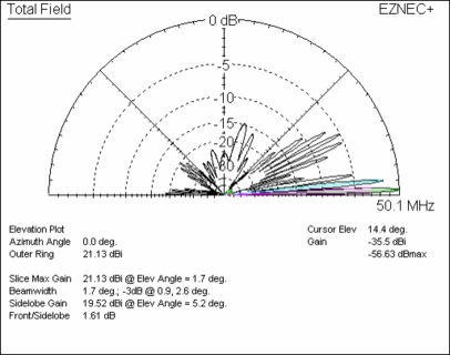
Figure 5: Six-meter stack at W8JI with traditional phasing of high antennas
With this pattern (figure 5), propagation would appear very spotty. A change in wave angle from just 2 degrees to 4 degrees could result in a 20 dB signal reduction. This is not a TOA problem. The problem is rooted in narrow main lobes with deep nulls between sharp peaks. If the signal arrival varied just 1-2 degrees, signal level could go from excellent readability to unreadable.
image012.gif

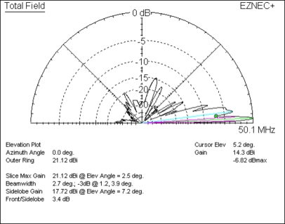
Figure 6:Stack at W8JI, same mean height, with progressive phase lag
One method of correcting the deep nulls is to add antennas and use a progressive phase shift between antennas. Since antennas normally fire in the direction of lagging phase, and since we want to fill nulls above the main lobe, the logical phase shift would be a progressive lagging phase shift with increasingly higher antennas.
In Figure 6, the addition of two more antennas with a lagging 30-degree progressive shift results in an array much less sensitive to wave angle. It has virtually the same field strength, within 6 dB, from 0.9 degrees up to 11 degrees. It still has nearly the same peak gain at very low angles to open the band, or to use when MUF just crosses the operating frequency, yet does not have the problem with 20-30 dB deep nulls if the wave angle shifts as little as 2 to 4 degrees from a lobe peak. Such a pattern would provide much more consistent signals over time.
Other Stacking Mistakes

We make many other stacking mistakes. I almost made one here at my house when I was considering stacking four 20-meter antennas. Fortunately, I put the myths about peak gain and takeoff angle aside and looked carefully at the nulls and beamwidth.
image014.gif

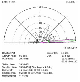
Figure 7: Proposed 20-meter four-antenna stack
My proposed four-antenna stack (figure 7) would have a 23.5 dB null at 9 degrees, which would be right in the hot spot of 20-meter signal a large portion of the time. It also would have less than dipole gain, sometimes significantly less, at any wave angle above 8 degrees. While it is mechanically easier and cheaper to stack multiple antennas one above the other, it is a huge waste of hardware because the pattern is just not that good.
image016.gif

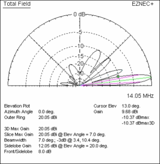
Figure 8: 2X2 H-stack for 20 meters
The antenna in figure 8 is an H arrangement of four antennas. This system uses half of the four-stack tower height, but requires either two towers side-by-side or one tower with two cross supports a full wavelength long. Since the antennas are small (four elements on a 26-foot long boom), I have decided that either arrangement would work.
Notice the peak gain is 20.05 dBi, which is about 11.5 dB over a dipole at optimum height. This system gives under 0.5 dB of peak gain, and gain is useful from well under 2 degrees up to 8 degrees. I have almost doubled the vertical beamwidth, making the antenna far less sensitive to wave angle variations.
image018.gif

Figure 9: H-stack with upper lagging phase
Lagging phase on upper antennas (figure 9) fills the deep pattern nulls while shifting the main lobe higher. It costs very little gain to do this, peak gain only decreasing 0.3 dB. Field strength is greater than a dipole at optimum height at any angle up to 20 degrees. By switching between these two patterns, this simple system covers most conditions of long distance propagation.
Summary

I hope the article shows why constructive conversation and debate, and looking at things from a different perspective, can lead to better understanding of systems and better antennas. If readers follow my thought processes as I progressed through these various antennas, they should notice I never considered take off angle at all. I looked at gain over the desired angles, focusing especially on nulls and null depth. My goal was maximum signal at all angles within the useful range of angles and directions. Nulls are especially poisonous to our signals. Few will notice a ten or more degree change in peak radiation angle, unless the lobe is very narrow and accompanied by deep nulls a few degrees off peak. If we focus on only one aspect, we can hurt ourselves in the end. We can obtain gain through a very narrow pattern, but if that pattern is full of nulls, we might lose a majority of contacts over time.
Sure, it is nice to brag and say we have 10 dBd gain. It is nice to say we have a low take off angle antenna, or a high angle for local work. Factually, take off angle by itself means nothing. Neither does peak gain. We need to focus on how well a planned antenna works over the most useful angles and directions. We need to pay particular attention to nulls, because the deep nulls, in particular multiple deep nulls, are really what prevents us from hearing and working what would otherwise be spectacular signals.

for those of us who operate dx exclusively the deep nulls at the higher elevation angles are our friends. we have also learned from experience, just as in the case of vhf and uhf antennas at 1, 2 or more wavelengths above ground and understanding that under these conditions the earth ground underneath these small antennas no longer has any effect or influence over the formation and shape of the radiation patterns, so too when elevated radial vertical monopoles operating on 11 meters are elevated at the feedpoint to heights of 5,6,7,8 and 9/4 wavelengths above earth ground and beyond this same scenario plays itself out, the only difference being that 1 wavelength at say 2 meters is a lot shorter than 1 wavelength at 11, the principle is the same. both directivity and maximum gain occur simultaneously at the more desirable, lower elevation angles for long distance communications as the feedpoint height is increased. the deep nulls at the higher elevation angles keep the receiver front end free of strong local signals so the signals arriving from other stations also via low elevation angle longpath take precedence in terms of signal strength. that's what antenna radiation effectiveness is all about, directing your signal where you want it to go while maximizing the strength of signals arriving from the same elevation angles at the receiver front end.

if i should at any time wish to increase coverage into areas at closer proximity i can gradually raise the elevation angle by simply lowering the support structure, more easily accomplished by lowering the tower remotely.

btw, both elevation angle and takeoff angle are just two terms describing the same parameter. i noticed a long time ago that w8ji never uses the second of the two terms when speaking with other licensed amateurs or providing references in amateur publications. i have also noticed that companies marketing and selling antennas like dxantennas.com love to use the latter of the two terms. fascinating.
 
Last edited:
I think I pretty much agree with most of that freecell, and the "high angle radiation for locals" would explain a few things I have been thinking, however...

how is it known that local stations are arriving at a higher angle and if so what are those angles approximately? It seems difficult to visualize... their RF does not go up @ 45 degrees (let's say 1km) and bend back down within 1km of atmosphere above and come back down at 45 degrees. That seems highly unlikely as there is no known daily phenomena (tropo ducting is occasional and not a permanent feature of the very low atmosphere). And how high is a higher angle ? 20/30/40/50 degrees.


The only other thought is that some atmospheric/space noise (I guess ionosphere refracted DX'ed noise is also a thing) maybe be coming in at quite steep angles (think NVIS and lower angles I suggest and approx 75 - 60 degrees) and some attenuation of high lobes may reduce some types of RX noise perception. I read this on models of an IMAX 2K with a variety of install methods, radials, no radials, isolation from mast and not etc.

Here it is:

http://www.copperelectronics.com/discus4/messages/7750/20506.html?1023340740

In any event whilst many multiples of wavelength might be the ideal for low TX/RX radiation only the lucky few ever manage yet dx gets worked every day. And it becomes even more difficult as wavelengths lengthen and verticals tend to be ground mounted and still work reasonably well.

Regarding take off and elevation angle.. I generally take them both to represent the lowest angle of radiation an antenna can produce... where as the spread from lowest to highest might be from 4 - 35 with a very good antenna, you would likely not wish for lobal break up anywhere in those angles.
 
Last edited:
To clarify my question... if a local station (let's say 20 miles away) radiates a signal at some high angle let's say 35-50 degrees... that angle will pass over ALL antennas local within 15-20 miles... so how can that radiation be RX'd at rx station antenna ? It will be way above the RX antenna, by possibly thousands of meters.

My suggestion would mean it is in fact lower angle radiation that is received... as the local station distance increases from any given RX location it is increasingly likely to be the very low angle radiation that makes it to any given station.

If I RX a station from 60miles away...that is likely to be their low angle radiation and not high angle radiation that is RX'd, that is my guess anyway.. and let's face it that is exactly what we are doing, having guesses.
 
Last edited:
I am venturing a simple fellow's reply as that is who I am and shall remain.
When viewing models others have produced I see most antennas that have high angle maximum rf radiation producing not a single spike to that high angle, but a generally rounded curve of rf pattern that shows radiation at all degrees from horizon upward. There is a degree of maximum gain along that curve, which may be at 40° elevation, but there is still some level of gain at other elevations. My "guess" is that the near by stations are communicating with each other because of the rf other than the maximum rf gain at 40° elevation.
RF comms do not limit themselves to the angle of maximum gain.
The model patterns are not about how far the "stations" are talking, but how strongly they talk into the distance. Close by everything is equal...
If I am in my mobile talking locally I can communicate only on the hill tops. When I drop into the hollows I lose contact with local stations. When I am in my mobile talking interstate long distance (CB DX) and I drive into a hollow from the hilltops I continue to maintain contact in most cases. This indicates to me the local contacts are lower angle comms, and the DX is higher angle in those cases. Maybe...
Or so says the simple ole fellow in the Arkansas Ozark Mtns.
 
Last edited:
I was starting to think to myself, what distance is local ? And what angle is high angle ? Already huge variables making generalization impossible.
 
All of this is anecdotal and hypothetical. All of it is conjecture and unprovable. All of it is for discussion purposes only, and nothing more. All of it is to form word pictures, and none of it is to make everybody a believer in UFOs nor anything else. All of it is simplification, not make the world a happier place.
And because simple gives some people indigestion doesn't mean it upsets my tummy.
And, that's why I engage very infrequently... I despise complication. Generalizations work for me most of the time. I'm not building a following so ....
 
Unfortunately the path between any Station A and station B is immensely complex whether we like that or not. Both stations RX/TX will be interdependent upon each others antenna type,set up, height, obstructions, ground type etc. The physics involved is virtually impossible to calculate.

Especially since radio wave propagation (as in the electro-magnetic fields traveling through the ether is not actually that well understood)

So yes I agree it is total guesswork, but I find it fun to think.
 
Yes.
It gives me a headache, and mostly serves to entertain only those who like complexity, and never finding a useful explanation.
I am a North and South guy. You go north until there is no more north and you are now going south. I am not an east or west guy. Going one or the other never leads anywhere. You perpetually go either, but never arrive. East is always unsatisfied, as is west. East and west are directions, but never destinations.
 
Well you are engaging in the discussion. I have a "common sense guess" and doubt that local comms are established from high angle radiation. Notwithstanding the endless possible RX/TX scenarios. Over a fairly flat city of 15miles diameter with a fairly flat landscape... high angle radiation does not appear logically to be the means of likely communication.

Given most CB antennas are within 5-15m of the earths surface (and as such quite low) it seems logical that low angles of radiation are the likely reason why they hear each other, unless there is some significant bending and reflection of waves of obstacles met en route.
 
  • Like
Reactions: HomerBB
Local comms are basically conducted via direct wave and do not involve ionospheric reflections. Because of this they are very low wave angles and we do not normally even talk about such angles for local direct wave comms because they are not really a factor. The more power you can direct at zero degrees the greater the local comms will be. Skywave comms is where elevation angles really come into play. The lower the angle the greater the distance possible if conditions are open to that part of the world at that time. As a side note, it is often possible on 80m that you can communicate by both direct wave and high angle skywave at the same time. Many times I have been talking to a "local" on 80m out anywhere from 20 to 100 miles and there is a consistency to signals and fading when direct wave is present while very significant fading and peaks when skywave comes into play. Direct wave has a pretty consistent range while varying skywave angles will cause a change in ranges. When we say the band went long we are basically saying that conditions are favouring the lower angles allowing much longer ranges.

As a separate side note, back in the hey days of shortwave broadcasting Radio Moscow had perfected the science of selecting the proper elevation angle into a target area. Just before broadcasting you could watch their carrier. You could watch it waver and peak and fade. Each peak was a bit stronger than the next and was not like normal atmospheric fading. The rate was much slower and other signals on the band at the same time. Just before sign-on the signal would peak massively and remain very steady for the entire broadcast. The Russians had perfected the ability to both slew the pattern horizontally of their huge curtain arrays as well as the elevation angle tp allow maximum signal into their intended target area. They would monitor the backscatter signal while adjusting the arrays. More signal back meant more was hitting the target area. It was calculated that they would have to have been running up to 10 megawatts at times into a fixed curtain array to achieve the signals they were able to achieve instead of the 500 kilowatts they were actually using and perfecting the angles.
 
I was thinking about this @Captain Kilowatt

"Because of this they are very low wave angles and we do not normally even talk about such angles for local direct wave comms because they are not really a factor."

How low an angle is "a very low wave angle" ? Given that all cb antenna's make local contacts surely that would make every CB antenna of any design i.e. 1/4 wave GPA, 1/2 wave end fed, T2LT (coaxial bazooka), 5/8 end fed, 5/8 dipole a good DX antenna which does not subjectively seem to be the case.

Is the suggestion that all CB antennas put out a similar signal at 0 - 3 degrees, and then differences start to appear between (as an example) 3-15 degrees, that make certain antennas better DX performers ? Is 0-3 degree radiation a bad DX angle ? Is that even achievable above actual ground ?

Or maybe they are all equals and that any difference at all is 100pct down to pure luck of the DX contact/atmospherics and any antenna for cb would have made the same contact at the same height and QTH (+/- matching losses and the small 1-2dB gain between the designs).

I have a distinct preference of 11m vertical as I am sure almost everyone does.

I have more questions than answers.

One thing about radio is it is amazing, especially DX, but there is always a a bit of a state of dissatisfaction that we cannot really know what is happening with our signals with any precision. You can build a better picture up over many hours operating a specific band usually. Maybe this is the element of mystery that keeps us hooked.
 
Last edited:
I post an overlaying model to illustrate a simple visual point.
In the overlay there are 4 vertical antenna types
1. A 5/8 wave with 4 x 108" slanted radials,
2. a 5/8 wave with 4 x 108" horizontal radials,
3. a 1/2 wave with 4 x 108" slanted radials, and
4. a 1/4 wave with radials.
All are mounted at 36' height.

The various influences of the positions of the radials horizontal vs slanted were the purpose of this model as done for me personally by @Marconi.
The point of posting it here is limited to the what the rf patterns look like along the 180° & 0° line. No matter the antenna type, and no matter which has more or less gain at other elevations they all have the same rf pathway along the 0° to 180° baseline for the same distance out from the vertical antennas. This, IMO, illustrates why mobiles and all types of vertical base antennas effectively communicate locally. Not much mystery here.
Screenshot_20201222-192249_Drive-01.jpeg
 
Last edited:
  • Like
Reactions: Shadetree Mechanic
I was thinking about this @Captain Kilowatt

"Because of this they are very low wave angles and we do not normally even talk about such angles for local direct wave comms because they are not really a factor."

How low an angle is "a very low wave angle" ? Given that all cb antenna's make local contacts surely that would make every CB antenna of any design i.e. 1/4 wave GPA, 1/2 wave end fed, T2LT (coaxial bazooka), 5/8 end fed, 5/8 dipole a good DX antenna which does not subjectively seem to be the case.

Is the suggestion that all CB antennas put out a similar signal at 0 - 3 degrees, and then differences start to appear between (as an example) 3-15 degrees, that make certain antennas better DX performers ? Is 0-3 degree radiation a bad DX angle ? Is that even achievable above actual ground ?

Or maybe they are all equals and that any difference at all is 100pct down to pure luck of the DX contact/atmospherics and any antenna for cb would have made the same contact at the same height and QTH (+/- matching losses and the small 1-2dB gain between the designs).

I have a distinct preference of 11m vertical as I am sure almost everyone does.

I have more questions than answers.

One thing about radio is it is amazing, especially DX, but there is always a a bit of a state of dissatisfaction that we cannot really know what is happening with our signals with any precision. You can build a better picture up over many hours operating a specific band usually. Maybe this is the element of mystery that keeps us hooked.

Basically ALL antennas radiate SOMETHING over all 180 degrees from horizon to horizon.They ALL differ in how much of that is radiated parallel to the ground which is where the useful signal for local contacts comes from. Furthermore each antenna is affected to a different degree by the quality of ground beneath the antenna. Lots of variables HOWEVER given those variables an antenna can be engineered to make the most of what it is capable of.You van tell a lot about an antenna by looking at the plots in both the horizontal and vertical planes where the horizontal plane shows the antenna pattern and the vertical plane shows the radiation over the various elevation angles.
 
  • Like
Reactions: HomerBB
Following the models they should all F2 layer dx great (actually virtually the same within 1-2dB) This is according to the models alone.

There is just one small issue, I can see that the black line representing the 1/2 wave mysteriously starts radiating at -15dB along the ground, why is that so ? I see only the green line of the 1/4 wave there 0 - 15dB along the ground.

Yes it does logically make sense that they radiate energy very low down say 0 - 1 degree thanks to you both for confirming your opinions. It is shame the model is not confirmatory in the close field.
 

dxChat
Help Users
  • No one is chatting at the moment.
  • @ Wildcat27:
    Hello I have a old school 2950 receives great on all modes and transmits great on AM but no transmit on SSB. Does anyone have any idea?
  • @ ButtFuzz:
    Good evening from Sunny Salem! What’s shaking?