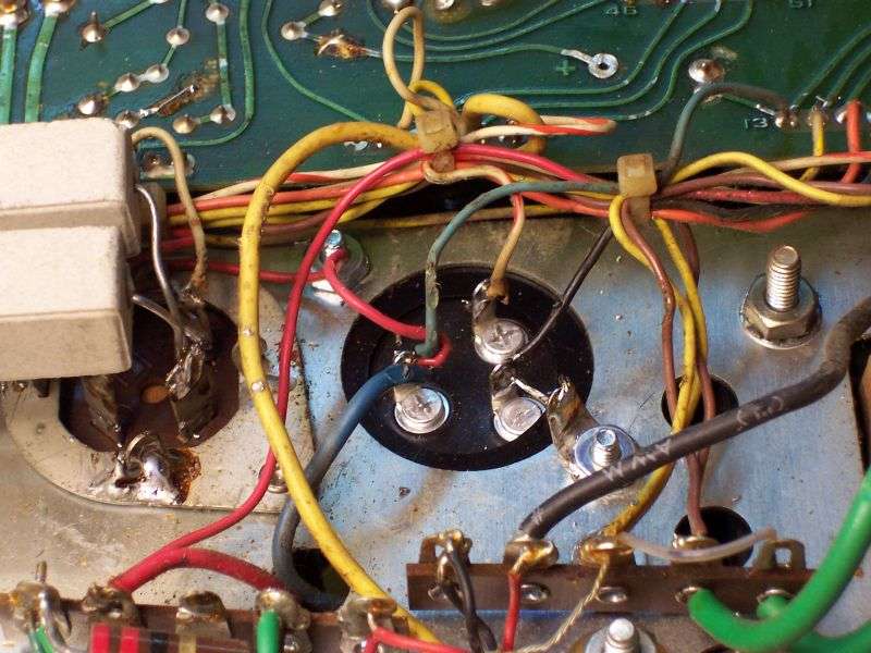
I am doing the restoration on a 1976 Tram D201 (2nd version). I will replace all electrolytic caps and high power resistors.
What are people using to replace the original Tram D201 Multi-section Caps?
I see that Mike's Radio Repair and some others appear to be using new JJ brand caps to replace the original multi-section caps. From the values that I see available, it looks like I could use the 40/20/20/20, and a 50/50, then use an additional 20uf... this would be 4X20uf for the 4x10uf in the schematic, a 40uf from the 40/20/20/20 for one of the 40uf on the schematic, and finally the dual 50/50 for the other two 40uf on the schematic in parallel.
So I could basically get all sections of the to original multi section caps taken care of with two new ones plus one single. I also read however that you one of these JJ caps could be a dual 100uf because the 40uf in parellel would effectively be 80uf and 100uf is close. But then I would have an unused 100uf which seems high to use for one of the other positions. What are you experienced techs using or what have the techs you sent your radios to using?
Thanks!

