• You can now help support WorldwideDX when you shop on Amazon at no additional cost to you! Simply follow this Shop on Amazon link first and a portion of any purchase is sent to WorldwideDX to help with site costs.
  • A Winner has been selected for the 2025 Radioddity Cyber Monday giveaway! Click Here to see who won!

TRC-451 dead no RX

That's kind of a problem in and of itself. On the upd2824 pin 10 is an output. As long as the chip has power, ground, and an input on pin 12, there should be a signal at pin 10 that's half the frequency of whatever is coming in on pin 12.

No signal there means either an internal fault in the chip, or an external component shorting to ground. The part that's connected to pin 10, C72, is a small cap to couple the 5.12 MHz into the tripler coil so I'm thinking it's probably not shorted to ground. But, weirder things have happened.
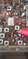
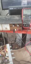
yes, Im inclined to believe the pll is shot..upto now I can assume the VCO circuit is working if the 16MhZ signal can be manipulated turning the L14 slug, right.. So just for kicks, can I use a variable ps, disengage pll pin 22 and inject 2.4 to 4 volts to the VCO at TP2? or how about injecting a 5.21MhZ signal at pll pin 10? can this be done with a TinySA at RF generator mode?
 
All I can say is you can try it out. The variable voltage to the VCO should result in what you think it will, frequency going up and down with the input voltage. You'd want to do that at pin 17. Pin 22 is the input from the loop downmix and won't affect the VCO.

I don't know if you can replace the 5.12 MHz signal with one from a TinySA, because I've never tried that particular trick. If the TinySA can provide enough drive it should work. End result should be VCO frequency minus 15.360 = signal at pll pin 22. So if you have 16.270 MHz at the VCO, you should have 0.91 MHz at pin 22. Likewise, if you have 16.710 MHz at the VCO, you should have 1.35 MHz at pin 22. Which happen to be the frequencies you'd expect to see for Channels 1 and 40, respectively.
 
  • Like
Reactions: Cable Guy
All I can say is you can try it out. The variable voltage to the VCO should result in what you think it will, frequency going up and down with the input voltage. You'd want to do that at pin 17. Pin 22 is the input from the loop downmix and won't affect the VCO.

I don't know if you can replace the 5.12 MHz signal with one from a TinySA, because I've never tried that particular trick. If the TinySA can provide enough drive it should work. End result should be VCO frequency minus 15.360 = signal at pll pin 22. So if you have 16.270 MHz at the VCO, you should have 0.91 MHz at pin 22. Likewise, if you have 16.710 MHz at the VCO, you should have 1.35 MHz at pin 22. Which happen to be the frequencies you'd expect to see for Channels 1 and 40, respectively.
Good morning..yup, that worked, the VCO trick so far..SuperBowl as loud as ever and even upper 11M..I had to input at TP2, injection at pin 17 didnt see any effect..right now, TP2 is at 2.81Vdc..going to try the TinySA trick now..
 

Attachments

  • 20250302_110250.jpg
    20250302_110250.jpg
    1.1 MB · Views: 5
  • 20250302_110314.jpg
    20250302_110314.jpg
    991.9 KB · Views: 5
  • Like
Reactions: TM86

dxChat
Help Users
  • No one is chatting at the moment.