• You can now help support WorldwideDX when you shop on Amazon at no additional cost to you! Simply follow this Shop on Amazon link first and a portion of any purchase is sent to WorldwideDX to help with site costs.

TRC-458, good receive, no transmit

rixdafix

561 Missouri
I Support WorldwideDX.com!
Dec 19, 2022
152
337
73
East Central Missouri
I ended up with two TRC-458s in a trade. One worked and the other had been hacked on pretty bad, probably be good for parts. Knowing they both have original caps, I rolled the dice and started using the one that works. A few days in I heard a bit of a hum and figured it was outside interference but in hindsight I believe it was the big cap in the power supply going out.

Anyway, I was talking to a friend and when i unkeyed he said he had lost my signal. I went ahead and recapped it (thanks Klondike Mike) and replaced the few random tantalums also. The proper values are all installed correctly and polarity is verified. It didn't fix the issue nor did i expect it to, I just wanted to make sure the caps were sorted before trying to find the issue.

I have excellent receive on am/ssb but zero transmit on either. The meter doesn't move on ssb when I key up and speak. On am key up the meter just barely moves and doesn't change when speaking. For what it's worth the meter does work fine on receive. I swapped relays temporarily, made no difference, contacts look fine on both also. The same antenna and coax works fine on a different radio. I only have a multimeter and a nanovna and very little knowledge of radio circuits. I'd really appreciate any guidance on bringing this back to life. Thanks
 
Last edited:
  • Like
Reactions: Klondike Mike

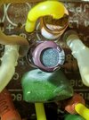
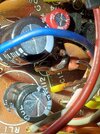
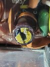
I forgot to mention D28 and R112 got hot enough to start melting the insulation covering the long wire leads. I pulled R112 and it tested fine, haven't tested D28 yet. Also tantalum C188 got hot enough too scar C183 and L33 on either side. Hot enough to be an issue? Bonus points for the broken L30 core. Just trying to throw a much info out there as possible. Thanks again.
20250604_173804.jpg20250604_173852.jpg20250604_173918.jpg
 
Last edited:
D28 is the receive-side regulator. Always runs a bit hot. Got in the habit of replacing R112 with a 2-Watt part. Or D28 and R112 get removed and a 7809 regulator gets strung onto the holes where R112 was, with the regulator's center pin into the anode hole (ground) where the zener was. Could be a prior owner turned up the power supply's voltage regulator high enough to cause excessive heat on those parts.

Check voltages on TR24. Should have 13-plus Volts on the collector (metal tab) about 9 Volts on the base and just over 8 Volts on the emitter. That circuit is controlled by 9-Volt zener D24. Either that pole of the relay has gone on strike, or something in TR24's regulator circuit. D24 doesn't work nearly as hard as D28 and doesn't typically get hot.

73
 
  • Like
Reactions: rixdafix
Thanks for that.

TR24 on tx
Collector 13.68v
Base 9.08v
Emitter 8.14v

I also checked the voltage at my power supply and it's right at 17 volts. I feel like that's high and should be closer to 13.8?
 
Yikes! 17v is too high. Back it down to 14 by adjusting the pot (TR302) on the power supply board. TP10 on the power supply board is where you can measure the output voltage.
I figured as much. Thanks!
Serves to explain the burned resistor and hot zener diode.

How 'bout the voltage at the emitter of TR24 when you key the mike?

73
8.14V

When I initially went to take voltage readings, I had my negative test lead connected to the chassis but was getting way wrong voltages. I connected the negative lead to a known ground on the board and got accurate readings. Is the chassis not grounded?

I also ordered Sams CB-207 so I can have a printed schematic in front of me.

Thanks again!
 
I figured as much. Thanks!

8.14V

When I initially went to take voltage readings, I had my negative test lead connected to the chassis but was getting way wrong voltages. I connected the negative lead to a known ground on the board and got accurate readings. Is the chassis not grounded?

I also ordered Sams CB-207 so I can have a printed schematic in front of me.

Thanks again!
No it's not. That was so, if the radio was used as a mobile with a positive ground, it would function properly. If used solely as a base, the board and the chassis ground can be connected together.
 
  • Like
Reactions: rixdafix
Yikes! 17v is too high. Back it down to 14 by adjusting the pot (TR302) on the power supply board. TP10 on the power supply board is where you can measure the output voltage.
Figured you meant RT301 and adjusting it made very little difference and actually the lowest voltage I see, right at 17v, is about dead center. Clockwise brings it up to maybe 17.5, counterclockwise never gets it below 17v. I went in small increments both ways after noting my starting point and took it almost to the stops. V never dropped below 17. It's back at the starting point which was pretty much dead center. Hmm.
 
Last edited:
An AC power supply that won't turn down below 17 Volts is broke. Pure and simple.

Biggest risk is the uPC1156 audio-power chip. It's made from unobtanium. Discontinued 40-plus years ago. Excess supply voltage is not kind to it.

If you have an external power supply to run it, the radio will last a lot longer that way.

Do you have another radio on hand you can use to eavesdrop on this one? Set it to the same channel and connect a coax jumper to it. Back the shell off the other end. This makes the exposed center pin into a half-inch long "sniffing" antenna. You can poke it into the area around the transmit mixer circuit and see if a weak transmit signal is being generated to start with. If so, the problem is downstream from the mixer transistor. If you hear nothing, the problem is either in the transmit mixer circuit or more likely upstream from it.

73
 
  • Like
Reactions: rixdafix
I do have an external power supply and several good working radios so that's not a problem. I'm going to build an rf probe for my multimeter, been wanting to for a while anyway, and when Sams CB#207 shows up I can do some probing and maybe get a better grip on this thing. I do want to get the power supply working and I have an identical parts radio but unfortunately it has "dc power only" written on the back and the (original) 3300uf cap is bulged bad so it may have some crispy components too. I imagine I'll have to send this to someone to get it aligned since I replaced the caps but I would like to at least get it operational first. I appreciate everyone's input very much.

73
 
Power supply is fixed. I checked all the voltages shown in the Sams schematic and found 6.16v instead of 15.06v at the base of TR302. I pulled and checked TR302, TR301, RT301, and R304. All checked fine. On a hunch, I lifted a leg of C410 and the capacitor check on my meter couldn't get a reading. The one in my parts radio checked fine so I swapped them and viola. It works. I've got 13.8v after adjusting RT301 a smidge! Now on to the tx issue...
 
  • Like
Reactions: USXDriver
Have a listen on a second monitor radio set to the same channel. What you can or can't hear this way is a large diagnostic clue. Might need to put a coax jumper on the monitor radio, back down the sleeve at the far end and use the exposed center pin as a sniffing antenna. If you still hear nothing this way, the trouble is either in the mixer transistor FET7 or upstream from it. Won't hurt to make sure the transmit voltage is reaching FET7 if the monitor radio is silent when this one is keyed.

73

Yesterday I was checking dc voltages as listed in Sams and so far everything checks out. I have a dummy load connected to the 458 and when I would key it up, the radio I was listening to dx on was picking up the signal, from about a foot away, so it's putting something out. My rf probe showed up yesterday so I'll get some rf volt readings too. Thanks for the suggestions.
 
So, transmitting into a dummy load, the mobile in my jeep, about twenty feet away, is able to clearly hear the 458 on AM and sideband. It's weak, but very clear. I'm wondering if I should hook my vertical up to the 458 and take the Jeep for a ride. I think my wife would humor me for a few more minutes of testing this morning. I need to get at least a cheap little watt meter as I've been relying on the meter in the radio. The meter did work fine before the radio quit transmitting. I then recapped it and had only tested through a dummy load while watching the meter. Meter works as expected on rx. Gonna feel kind of silly if it's actually transmitting and I have a meter tx circuit issue...


Write your reply...
dxChat
Help Users
  • No one is chatting at the moment.


      You do not have the permission to use the chat.