Ok it's transmitting, just weak. Rx into mobile sounds good up to about 1/2 mile out then quickly drops to no copy by about a mile and a half.
You are using an out of date browser. It may not display this or other websites correctly.
You should upgrade or use an alternative browser.
You should upgrade or use an alternative browser.
-
You can now help support WorldwideDX when you shop on Amazon at no additional cost to you! Simply follow this Shop on Amazon link first and a portion of any purchase is sent to WorldwideDX to help with site costs.
TRC-458, good receive, no transmit
- Thread starter rixdafix
- Start date
More info. I measured rf voltage through a few points in the driver and final stages on AM into dummy load.
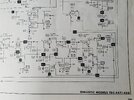
Referring to the schematic;
location 150 reads .402v dead key going up to about .480v with auuuudio.
155 reads 14.8v dk up to 22.0v with audio.
158 reads 1.12v dk up to 1.35v with audio.
Problem in final circuit?
Measured DC voltages at tr45,44,43 on dk look ok except,
TR43 base reads .98v (Sam says .59v), collector reads 5.3v.
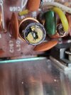
One thing I noticed is C174 (pictured) looks like it got hot. Almost looks bubbled up a little as did C410 in the power supply which ended up being faulty. I wonder if I should swap that out.
Last thing is that L30. I haven't touched it and the radio was working, until, it didn't but i hate that busted slug. My parts radio has an untouched L30. Worth replacing? I don't expect it to fix my issue but yeah. Thanks


Last edited:
Definitely replace C174 if it is bulged. Ceramic capacitors are cheap. Replace TR43 as well, it's toast if you have .98v at the base. And Yes, replace the slug too, that is very important. That coil is part of the matching network that transforms the low impedance of the final to the 50ohm of the output filter. If that is not tuned right, the final will see high SWR and can burn up. I assume that is what happened here. You will want to adjust that slug so that you have maximum power transfer into the pi filter as indicated by a peak in the RF voltage at the antenna jack.
EXTREMELY IMPORTANT, do NOT try to peak that coil by the voltage at node 126. It may appear to be the right place to do that, but its not, and the voltage will continue to climb as the inductance exceeds the optimal point (just checked in simsmith). Make sure you peak that measuring RF voltage at the ANTENNA JACK with a dummy load connected (not antenna). Don't touch L27 either. That can be a different conversation once we get it putting out power.
EXTREMELY IMPORTANT, do NOT try to peak that coil by the voltage at node 126. It may appear to be the right place to do that, but its not, and the voltage will continue to climb as the inductance exceeds the optimal point (just checked in simsmith). Make sure you peak that measuring RF voltage at the ANTENNA JACK with a dummy load connected (not antenna). Don't touch L27 either. That can be a different conversation once we get it putting out power.
If you attempt to pull the good slug out of the parts radio and it doesn't want to turn, just stop. These usually break because there is a little wax in there to keep them from moving once set and people try forcing them to turn. Use hot air (lowest setting) to soften the wax if it seems stuck.
I use hot air, but before I got my first rework station I would use the tip of the soldering iron on low and just touch the slug for a few seconds. This is more difficult with the smaller slugs and you have to be careful not to touch the threads of the sleeve. Then start slowly working the slug back and forth until it frees up. But for sure, hot air is the way to go either way.
I wonder if it would be easier to swap the whole thing. I've got a good solder sucker and temp adjustable soldering station I used for the recap. The slug in the parts radio is still sealed, never been turned.I use hot air, but before I got my first rework station I would use the tip of the soldering iron on low and just touch the slug for a few seconds. This is more difficult with the smaller slugs and you have to be careful not to touch the threads of the sleeve. Then start slowly working the slug back and forth until it frees up. But for sure, hot air is the way to go either way.
For that size slug, it's easier to just replace the slug than replace the whole coil/slug assembly. If it were the smaller metal cans and the slug was crushed, unsoldering the whole can is the way to go as the slug has a slot on both ends and you can either replace the can or back the slug out from the bottom of the can to replace just the slug. Do you have a heat gun? If so, that is definitely the way to go.I wonder if it would be easier to swap the whole thing. I've got a good solder sucker and temp adjustable soldering station I used for the recap. The slug in the parts radio is still sealed, never been turned.
Actually, you could probably use a hair dryer as the wax is just beeswax and has a pretty low melting point. Once you get the slug moving, it often won't seize up again.
Hair dryer worked like a champ, slug swapped. On to C174 and TR43. I have no idea if the final in the donor radio is good but I'm going to pull it first. Would a simple transistor junction voltage drop check using the diode function on my meter be of any value before installing?
Yes! Red lead on base, black lead on the other two. Both should show a diode drop.
And make a note on a piece of tape on the bezel so you don't forget to go back and tune that matching slug once you get a working final in there. You don't want to forget and start transmitting for long periods without having set that.
And make a note on a piece of tape on the bezel so you don't forget to go back and tune that matching slug once you get a working final in there. You don't want to forget and start transmitting for long periods without having set that.
Last edited:
Sweet. Got the donor out, drops a little over .6v at both junctions and OL with leads reversed. I need to order some heat sink paste and umm a watt meter. Be a couple of days and I'll get these bits in and see where I'm at with this classic. Thanks you guys.
This tells you that the full power-supply voltage the radio feeds to the final transistor's collector came shooting out of the base lead. That lead should be the input. There will most often be collateral damage in the final base circuit. D51, R304, R205, R219 and the trimpot VR16 should all be checked. The risk is that the new final's base lead will have way too much voltage on it and poof itself the first time the mike is keyed. Or no voltage at all. Makes AM a bit wimpy and sideband sound nasty when there is no base bias voltage.old final drops .006v base to collector,
Collateral damage to components on the final's input side should get checked before you put power to the new final. It can poof right quickly if the base voltage is too high.
73
Roger that. I'll lift some legs and test this evening. Good stuff.D51, R304, R205, R219 and the trimpot VR16 should all be checked.
dxChat
- No one is chatting at the moment.
-
@ Hambones amps:Does anyone know if you can replace the 2290 in a galaxy dx 93t twin turbine with a 2sc2879 red dot? If so, what would have to be tuned?
-
-
@ ShadowDelaware:Hambones the entire amp section would have to be retuned, and the rf transformers re wrapped.
-
